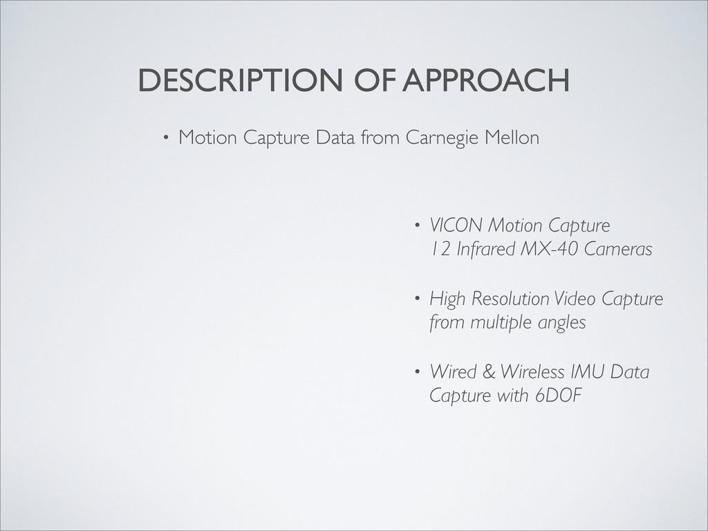
and model 3-axis 6-DOF human arm motion for a variety of different applications. • Inertial Measurement Units (IMUs) gaining traction due to rapid advances in technology and lower costs. • Large source of inaccuracy arising from the integration of angular velocities (gyroscope) and acceleration (accelerometer).
Accelerometers Published in 1996 by Sakaguchi, et al. • Two axis joint motion monitoring through the use of IMU data. • Joint Motion Monitoring by Accelerometers Set at Both Near Sides Around the Joint Published in 1998 by Kurata, et al. • Derived a model to extract joint angles from IMU data.
and Gyroscope Measurements Published in 2008 by Hyde, et al. • Derived a model which was used as a basis in this project • Reducing Drifts in the Inertial Measurement of Wrist and Elbow Positions Published in 2010 by Zhou, et al. • Used a Kalman filter to reduce error and improve accuracy of IMU data.
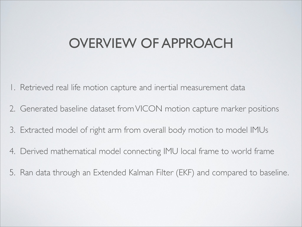
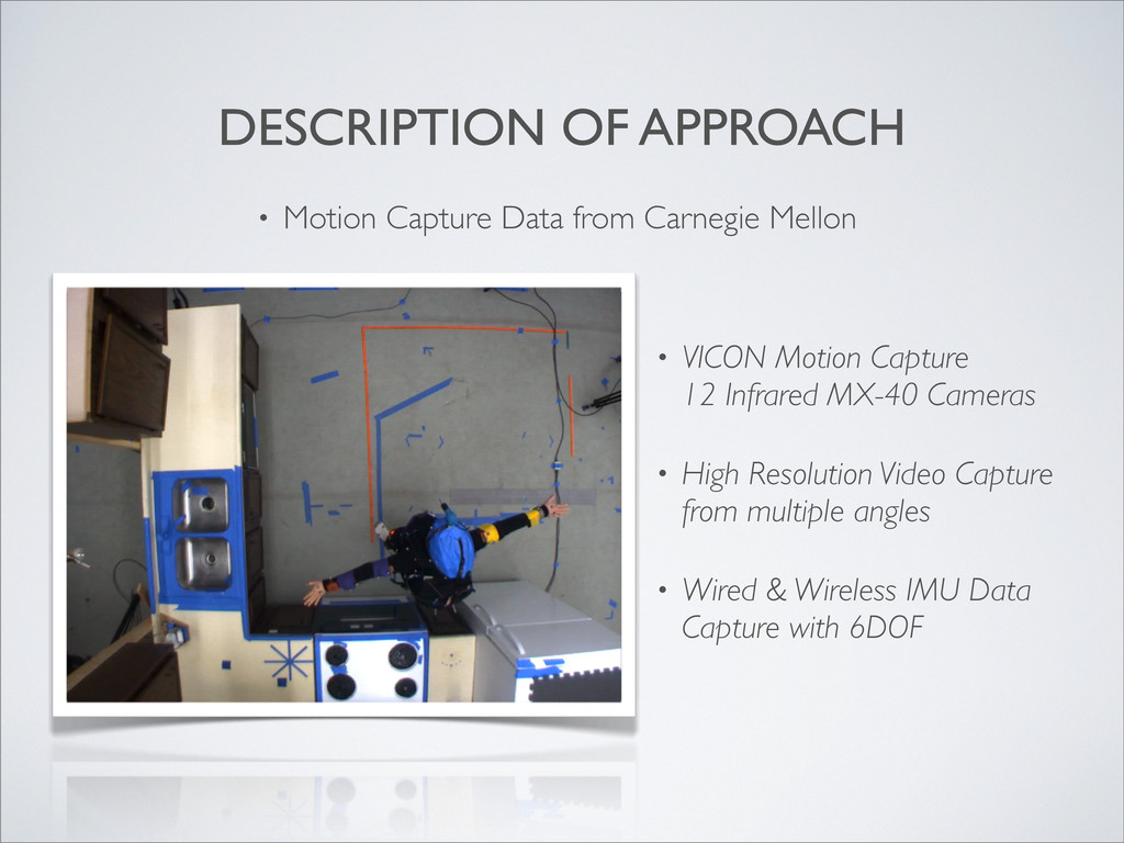
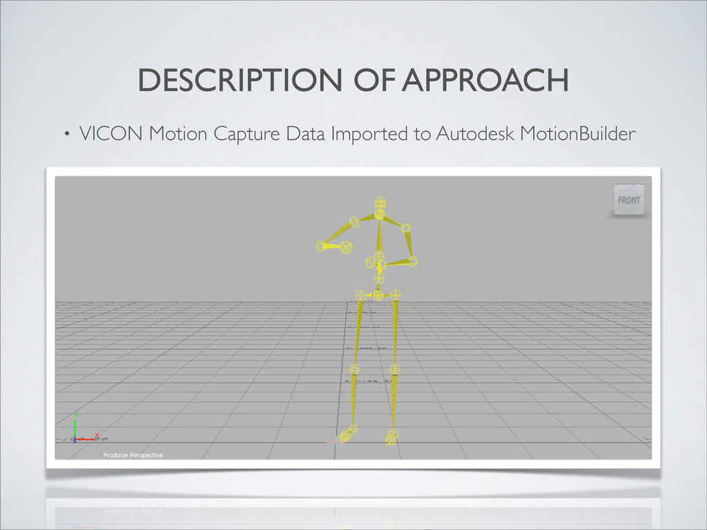
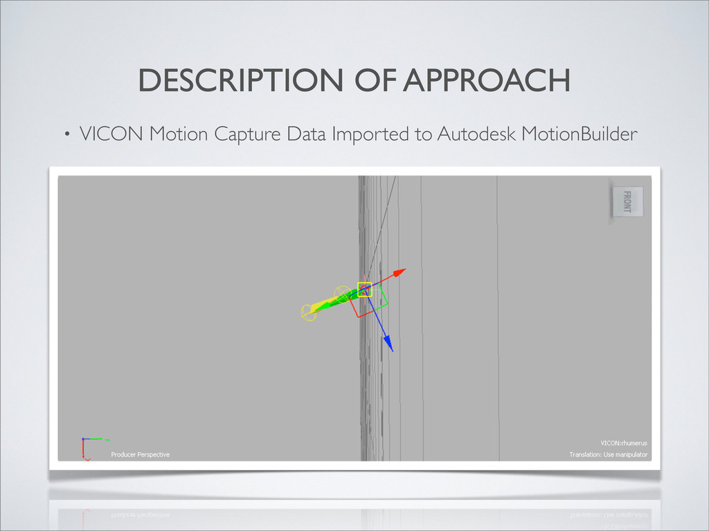
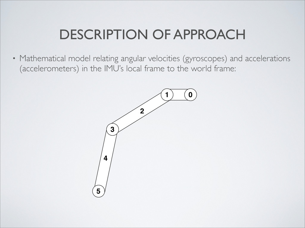
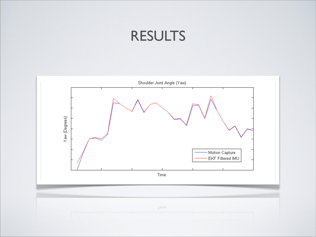
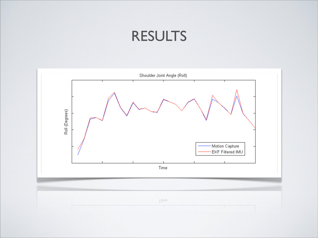
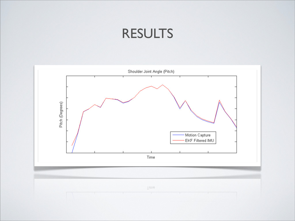
inertial measurement data 2. Generated baseline dataset from VICON motion capture marker positions 3. Extracted model of right arm from overall body motion to model IMUs 4. Derived mathematical model connecting IMU local frame to world frame 5. Ran data through an Extended Kalman Filter (EKF) and compared to baseline.
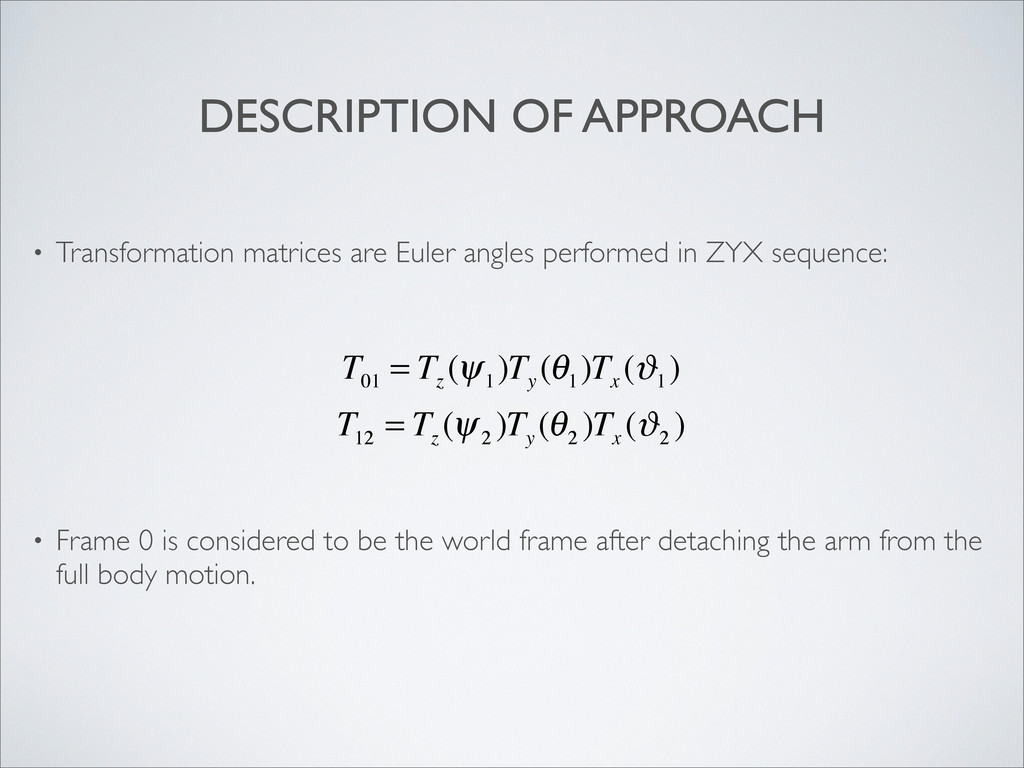
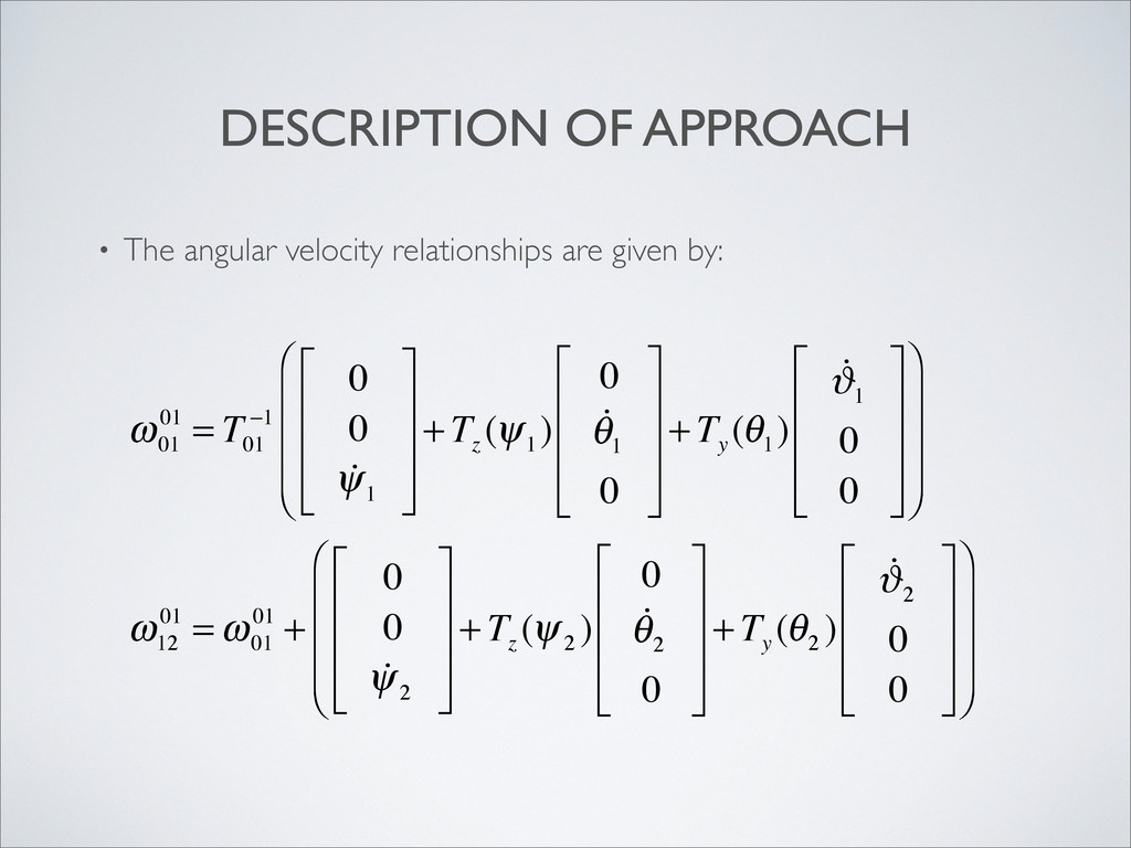
in ZYX sequence: • Frame 0 is considered to be the world frame after detaching the arm from the full body motion. T 01 = T z (ψ 1 )T y (θ 1 )T x (ϑ 1 ) T 12 = T z (ψ 2 )T y (θ 2 )T x (ϑ 2 )
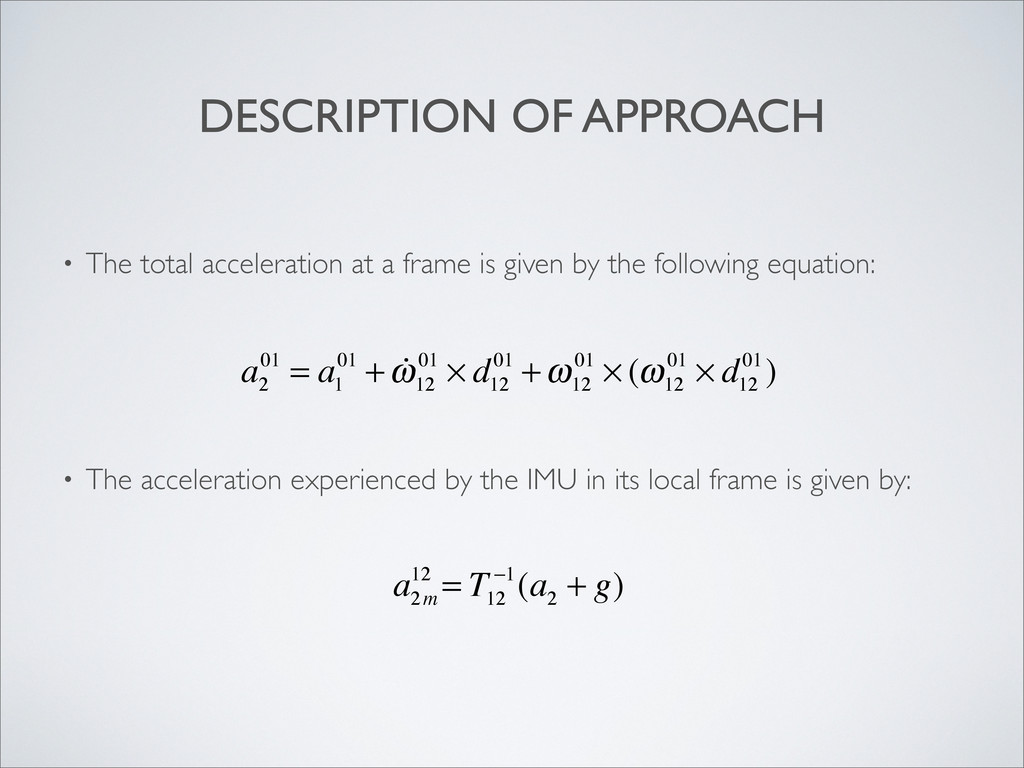
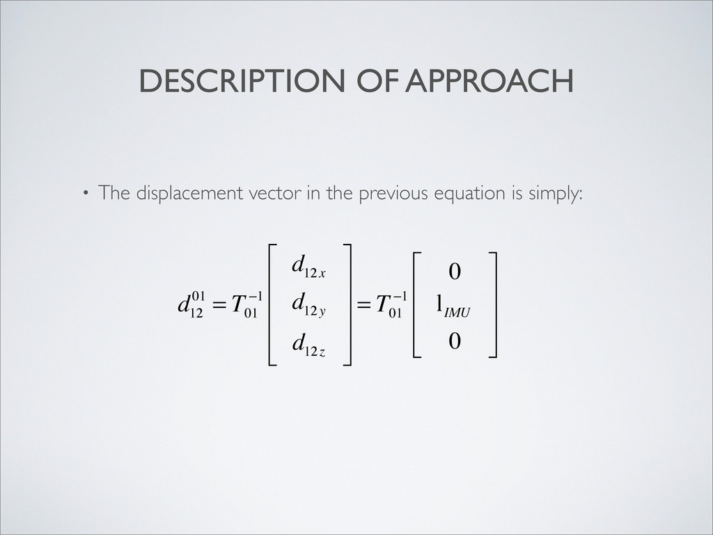
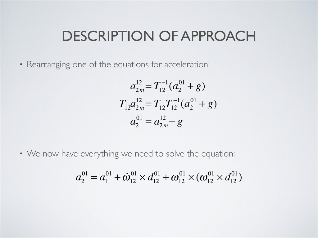
is given by the following equation: • The acceleration experienced by the IMU in its local frame is given by: a 2m 12 = T 12 −1(a 2 + g) a 2 01 = a 1 01 + ω 12 01 × d 12 01 +ω 12 01 × (ω 12 01 × d 12 01)
2 01 + g) T 12 a 2m 12 = T 12 T 12 −1(a 2 01 + g) a 2 01 = a 2m 12 − g a 2 01 = a 1 01 + ω 12 01 × d 12 01 +ω 12 01 × (ω 12 01 × d 12 01) • Rearranging one of the equations for acceleration: • We now have everything we need to solve the equation:
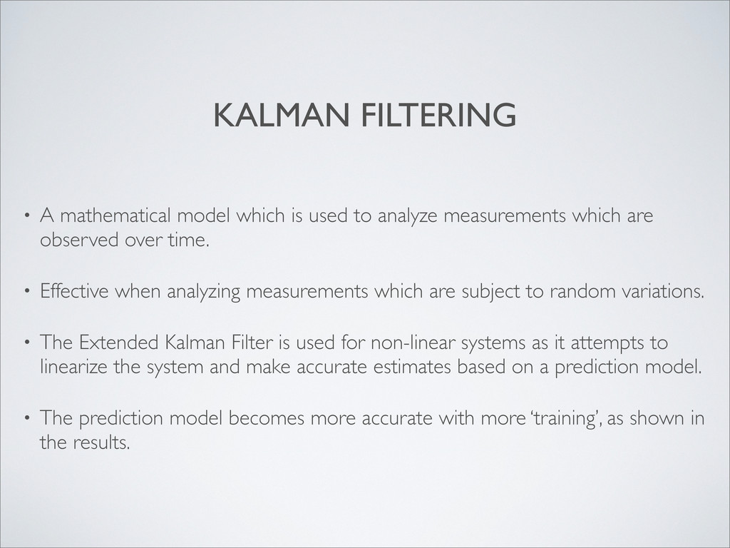
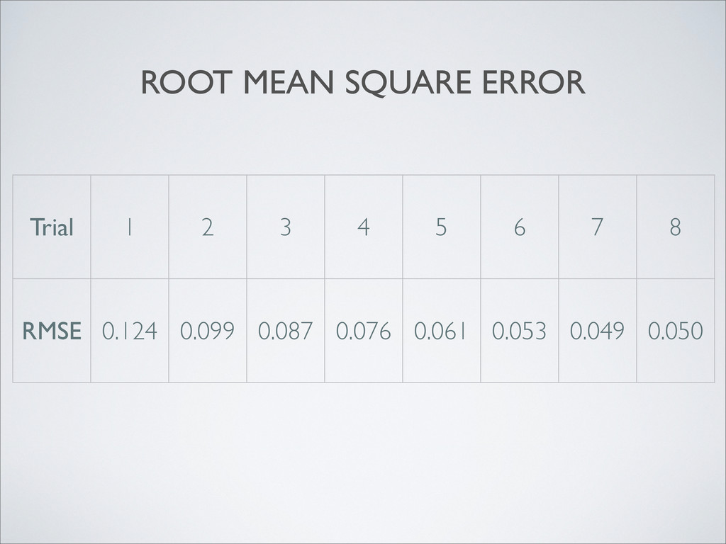
analyze measurements which are observed over time. • Effective when analyzing measurements which are subject to random variations. • The Extended Kalman Filter is used for non-linear systems as it attempts to linearize the system and make accurate estimates based on a prediction model. • The prediction model becomes more accurate with more ‘training’, as shown in the results.
of joint angles as shown with the comparison to motion capture data from the VICON camera’s. • For applications where computational power requirements is not an issue, EKC or an equivalent algorithm should be implemented.