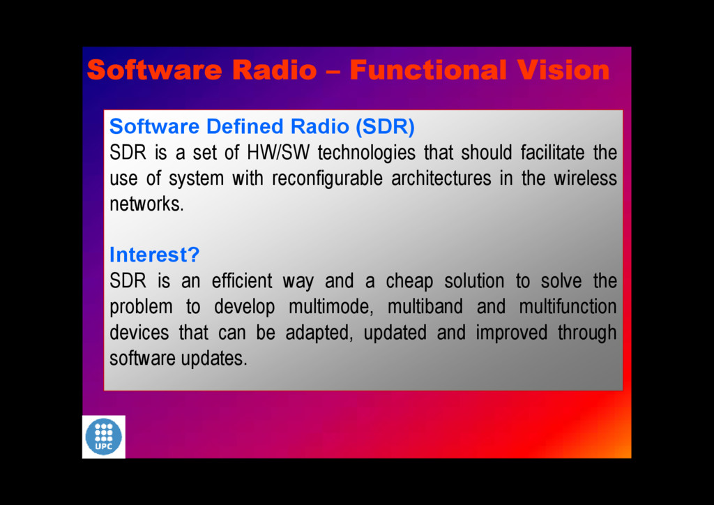
technologies that should facilitate the use of system with reconfigurable architectures in the wireless networks. Interest? SDR is an efficient way and a cheap solution to solve the problem to develop multimode, multiband and multifunction devices that can be adapted, updated and improved through software updates. Software Radio – Functional Vision
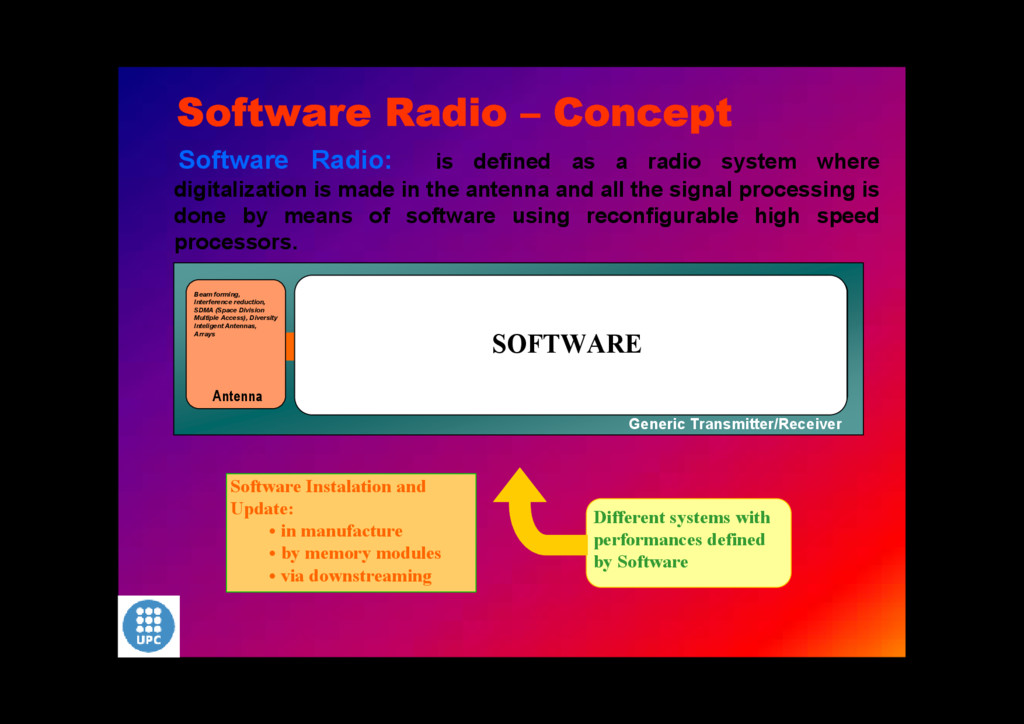
is made in the antenna and all the signal processing is done by means of software using reconfigurable high speed processors. Different systems with performances defined by Software Software Instalation and Update: • in manufacture • by memory modules • via downstreaming Software Radio – Concept Antenna Beam forming, Interference reduction, SDMA (Space Division Multiple Access), Diversity Inteligent Antennas, Arrays RF Conversion FI Processing Base Band Bits Flow Source RF/FI Filtering Power Amplifier RF to FI Conversion Sampling. AD & DA Digital Channel Filtering Base Band Conversion Frequency Synthesis Carrier Recovery Modulation/Demodulation Pre-distortion Channel Estimation Equalisation Decodification Synchronization Users Multiplexing Estimation and Quality Control Frame alignment Encryption Signalling, Control, Management and Maintenance Voice and Video Codecs, etc Generic Transmitter/Receiver SOFTWARE
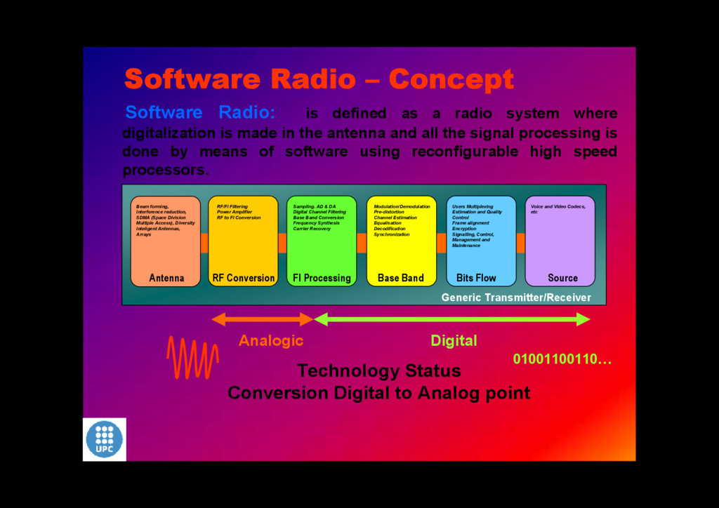
is made in the antenna and all the signal processing is done by means of software using reconfigurable high speed processors. Software Radio – Concept Antenna Beam forming, Interference reduction, SDMA (Space Division Multiple Access), Diversity Inteligent Antennas, Arrays RF Conversion FI Processing Base Band Bits Flow Source RF/FI Filtering Power Amplifier RF to FI Conversion Sampling. AD & DA Digital Channel Filtering Base Band Conversion Frequency Synthesis Carrier Recovery Modulation/Demodulation Pre-distortion Channel Estimation Equalisation Decodification Synchronization Users Multiplexing Estimation and Quality Control Frame alignment Encryption Signalling, Control, Management and Maintenance Voice and Video Codecs, etc Generic Transmitter/Receiver Technology Status Conversion Digital to Analog point Analogic Digital 01001100110…
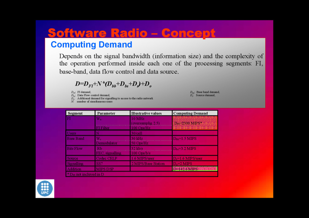
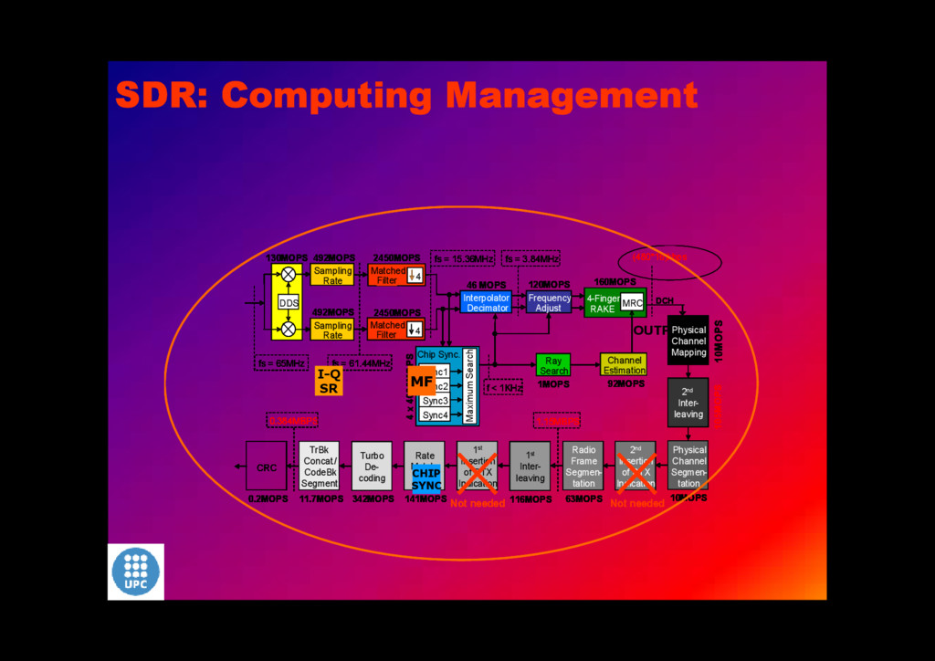
the complexity of the operation performed inside each one of the processing segments: FI, base-band, data flow control and data source. D=D FI +N*(D bb +D bs +D s )+D o D FI: FI demand, D bb: Base band demand, D bs: Data Flow control demand, D s: Source demand, D o: Additional demand for signalling to access to the radio network N: number of simultaneous users Segment Parameter Illustrative values Computing Demand Wa 10 MHz (oversamplig 2.5) FI FI Filter 100 Ops/Hz DFI=2500 MIPS* Users N 30/cell Wc 30 kHz Base Band Demodulator 50 Ops/Hz Dbb=1.5 MIPS Rb 32 kb/s Bits Flow FEC, signalling 100 Ops/b/s Dbs=3.2 MIPS Source Codec CELP 1.6 MIPS/user Ds=1.6 MIPS/user Signalling SS7 2 MIPS/Base Station Do=2 MIPS Addition MIPS DSP D=142.6 MIPS * DFI not incluyed in D Software Radio – Concept
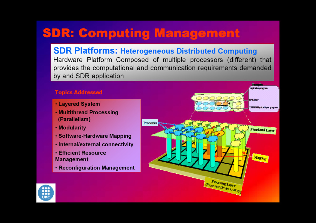
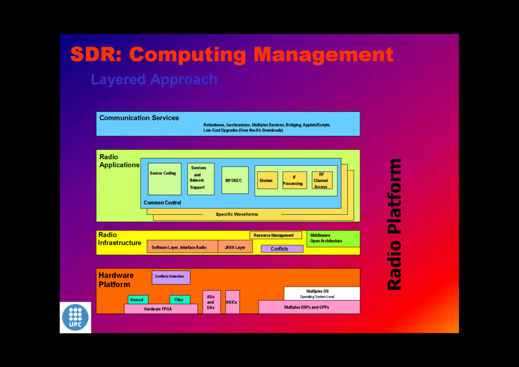
Aplicaciones Radio Codificación Decodificación Fuente Servicios y Soporte de Red INFOSEC Codificación Decodificación Fuente Modem IF Processing RF Channel Access Formas de onda especificas Infraestrucrtura Real -Time CORBA/IDL Capa Tunel Capa JAVA Conflictos Gestión Recursos Middleware Arquitectura Abierta Control Conjunto Detección de Conflictos Hardware FPGA ADs y DAs ASICs Multiples Multiples OS Nivel de Sistema Operativo Filtro Demod Plataforma Hardware Communication Services Robustness, Isochronisms, Multiples Services, Bridging, Applets/Scripts, Low-Cost Upgrades (Over-the-Air-Downloads) Radio Applications Codificación Decodificación Fuente Services and Network Support INFOSEC Source Coding Modem IF Processing RF Channel Access Specific Waveforms Radio Infrastructure Software Layer, Interface Radio JAVA Layer Conflicts Resource Management Middleware Open Architecture Common Control Conflicts Detection Hardware FPGA ADs and DAs ASICs Multiples DSPs and GPPs Multiples OS Operating System Level Filter Demod Hardware Platform Radio Platform Layered Approach SDR: Computing Management
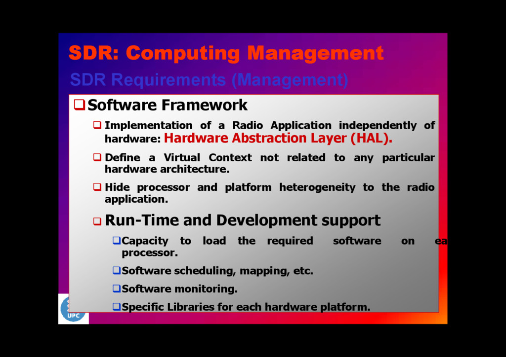
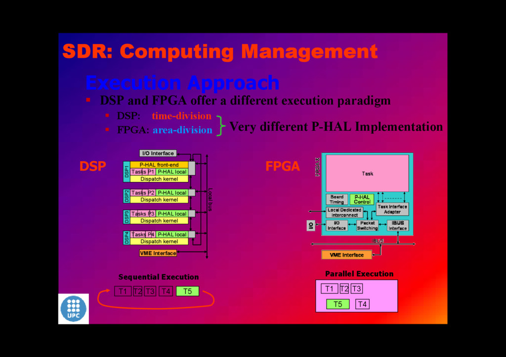
Application independently of hardware: Hardware Abstraction Layer (HAL). Define a Virtual Context not related to any particular hardware architecture. Hide processor and platform heterogeneity to the radio application. Run-Time and Development support Capacity to load the required software on each processor. Software scheduling, mapping, etc. Software monitoring. Specific Libraries for each hardware platform. SDR: Computing Management
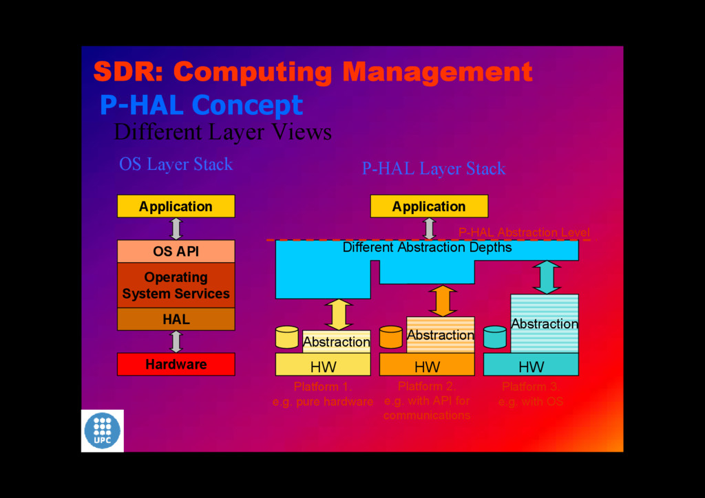
Views OS Layer Stack Platform 2. e.g. with API for communications HW HW HW Abstraction Abstraction Abstraction Different Abstraction Depths Application P-HAL Layer Stack P-HAL Abstraction Level Platform 3. e.g. with OS Platform 1. e.g. pure hardware P-HAL Concept SDR: Computing Management
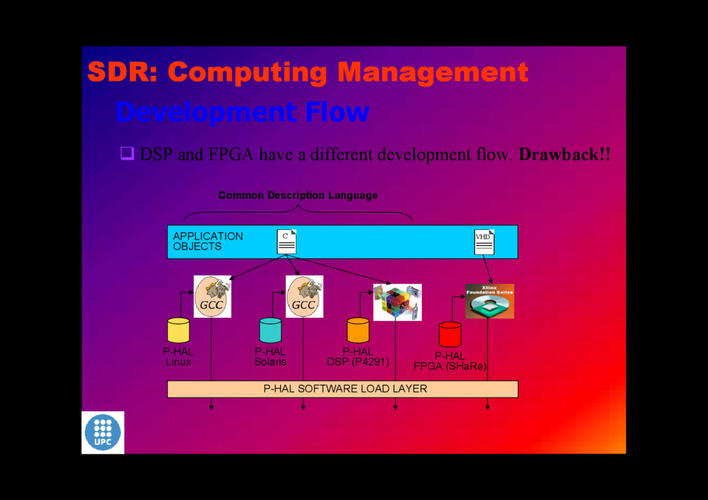
P-HAL DSP (P4291) P-HAL FPGA (SHaRe) P-HAL SOFTWARE LOAD LAYER Development Flow DSP and FPGA have a different development flow. Drawback!! Common Description Language SDR: Computing Management
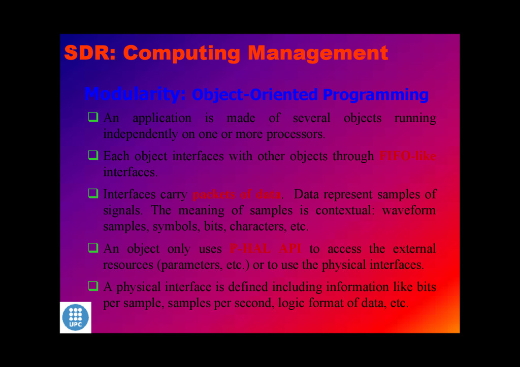
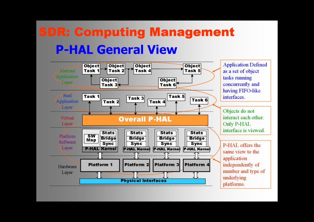
objects running independently on one or more processors. Each object interfaces with other objects through FIFO-like interfaces. Interfaces carry packets of data. Data represent samples of signals. The meaning of samples is contextual: waveform samples, symbols, bits, characters, etc. An object only uses P-HAL API to access the external resources (parameters, etc.) or to use the physical interfaces. A physical interface is defined including information like bits per sample, samples per second, logic format of data, etc. SDR: Computing Management
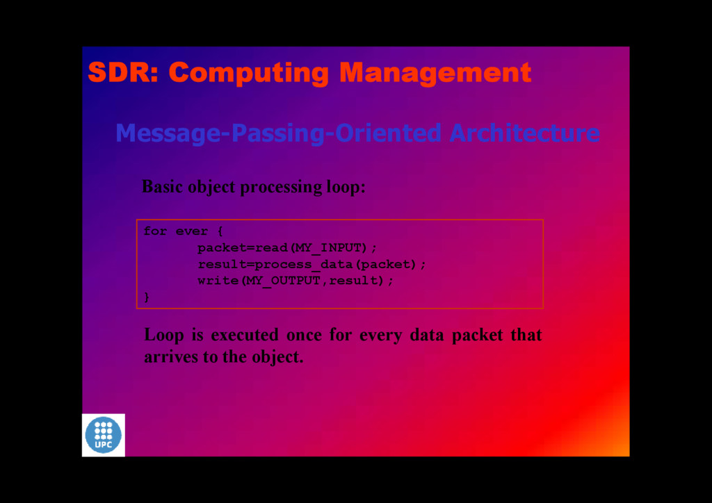
result=process_data(packet); write(MY_OUTPUT,result); } Loop is executed once for every data packet that arrives to the object. SDR: Computing Management
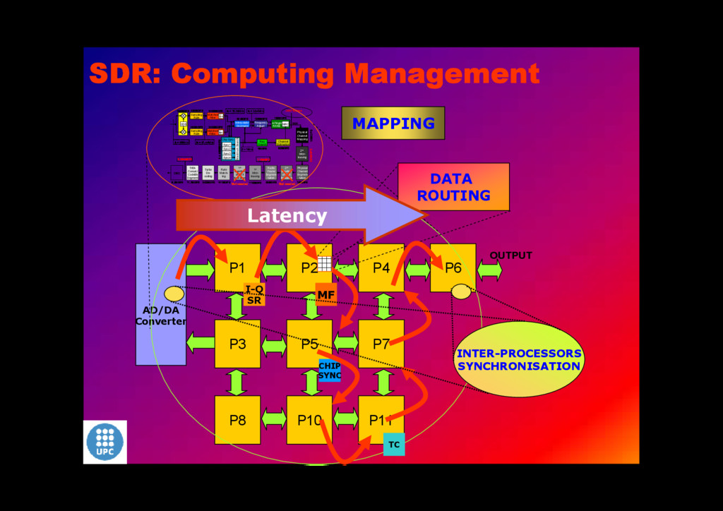
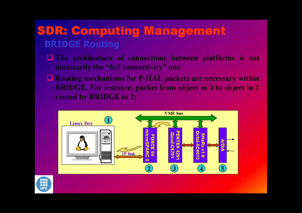
not necessarily the “full connectivity” one. Routing mechanisms for P-HAL packets are necessary within BRIDGE. For instance, packet from object in 3 to object in 1 routed by BRIDGE in 2: Linux Box FORCE 5V microSPARC II PENTEK 4291 Quad-C6701 SHaRe v1.0 Octal-XC4013 A/D/A VME bus IP link 4 1 2 3 5 SDR: Computing Management
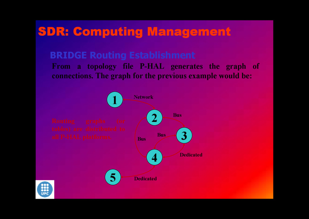
graph of connections. The graph for the previous example would be: 1 3 2 4 5 Network Bus Bus Bus Dedicated Dedicated Routing graphs (or tables) are distributed to all P-HAL platforms. SDR: Computing Management
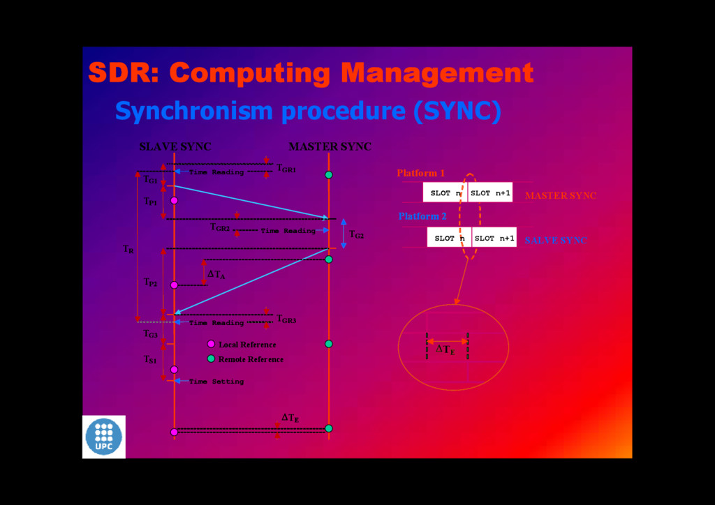
of adequate time references is necessary. Each platform has its own time counter (or RTC) that must be aligned with other time counters. The references can be obtained only through communications interfaces. That is, precision in synchronism is based on communications reliability. Synchronism is performed regularly to overcome the differences in the respective local oscillators. Time adjustment is crucial for the correct behaviour of the application but a relatively slight misalignment is not critical because of the execution time framework. SDR: Computing Management
to control the temporal evolution of applications. PIPELINED execution. Every application object gets CPU time within every time slot to process data packets. P-HAL schedules the execution of the object. The instant within the slot where the object goes to execution is immaterial. SDR: Computing Management
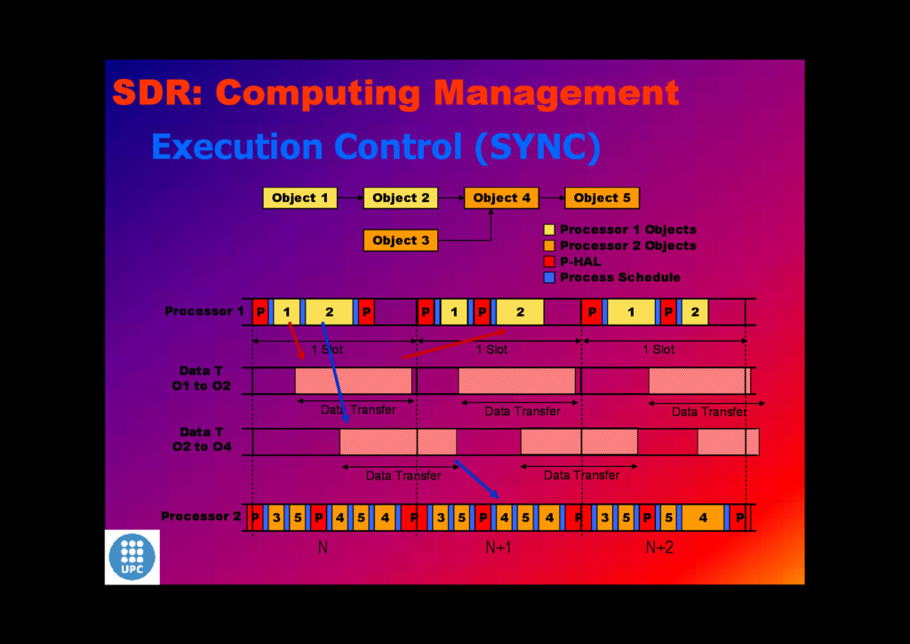
P Object 1 Object 2 Object 3 Object 4 Object 5 Processor 1 Objects Processor 2 Objects Processor 1 Data T O1 to O2 1 2 1 2 P P P 3 5 4 P 5 4 3 5 4 P 5 3 5 4 P 5 4 2 1 P P P-HAL Process Schedule 1 Slot Data Transfer 1 Slot Processor 2 1 Slot Data T O2 to O4 Data Transfer Data Transfer Data Transfer Data Transfer N N+1 N+2 P P P P P Object 1 Object 2 Object 3 Object 4 Object 5 Processor 1 Objects Processor 2 Objects Processor 1 Data T O1 to O2 1 2 1 2 P P P 3 5 4 P 5 4 3 5 4 P 5 3 5 4 P 5 4 2 1 P P P-HAL Process Schedule 1 Slot Data Transfer 1 Slot Processor 2 1 Slot Data T O2 to O4 Data Transfer Data Transfer Data Transfer Data Transfer P P P P P Object 1 Object 2 Object 3 Object 4 Object 5 Processor 1 Objects Processor 2 Objects Processor 1 Data T O1 to O2 1 2 1 2 P P P 3 5 4 P 5 4 3 5 4 P 5 3 5 4 P 5 4 2 1 P P P-HAL Process Schedule 1 Slot Data Transfer 1 Slot Processor 2 1 Slot Data T O2 to O4 Data Transfer Data Transfer Data Transfer Data Transfer N N+1 N+2
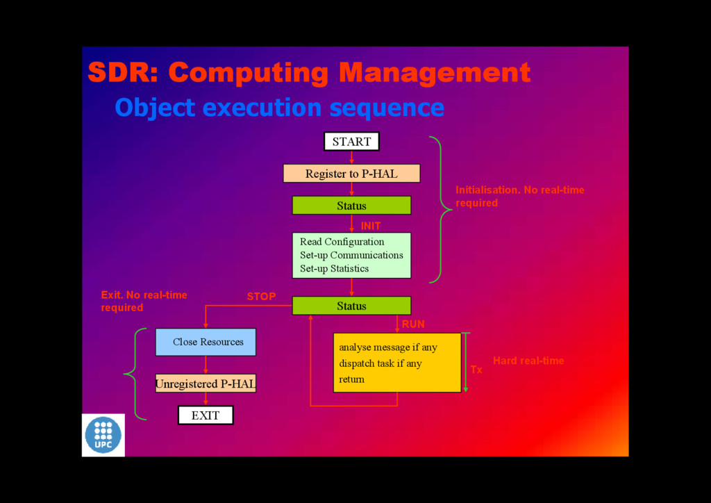
Communications Set-up Statistics Register to P-HAL INIT Close Resources STOP analyse message if any dispatch task if any return Unregistered P-HAL RUN START EXIT Tx Status Status Hard real-time Exit. No real-time required SDR: Computing Management
TABLE) DATA LOGICAL INTERFACES: FIFO-LIKE PHYSICAL INTERFACES P-HAL RAM ADAPTATION LOGICAL RAM INTERFACE SBSRAM SDRAM SRAM MEMORY POOL ENABLE/DISABLE/RESET STATUS MONITOR P-HAL CONTROL PORT CONTROL WORD (4 – 8 bits) BIDIRECTIONAL SERIAL PORT FOR REQUESTS (IN/OUT) PHYSICAL INTERFACE TIME REGISTER TIME STAMP ON-BOARD TIME INTERFACE SDR: Computing Management
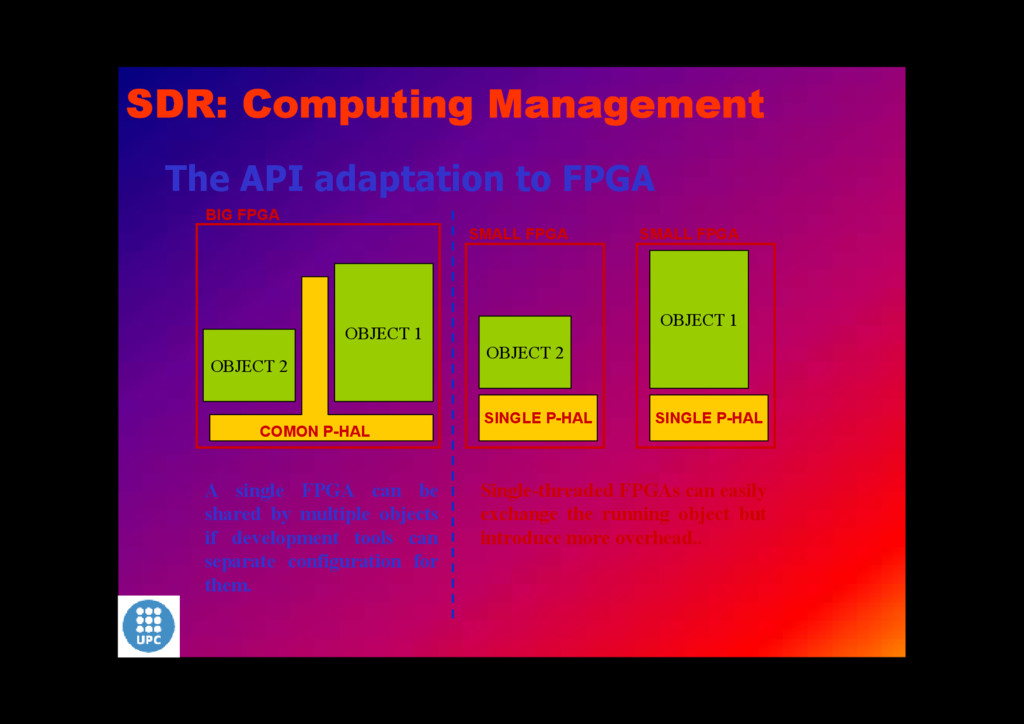
1 OBJECT 2 SMALL FPGA SINGLE P-HAL OBJECT 2 SMALL FPGA SINGLE P-HAL OBJECT 1 A single FPGA can be shared by multiple objects if development tools can separate configuration for them. Single-threaded FPGAs can easily exchange the running object but introduce more overhead.. SDR: Computing Management
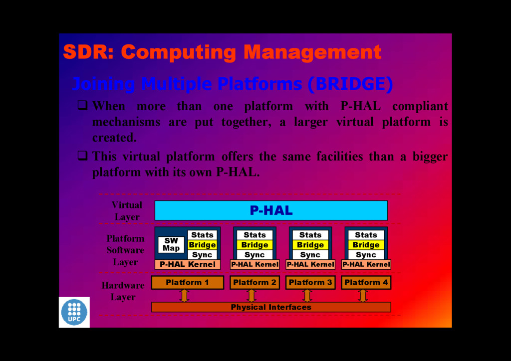
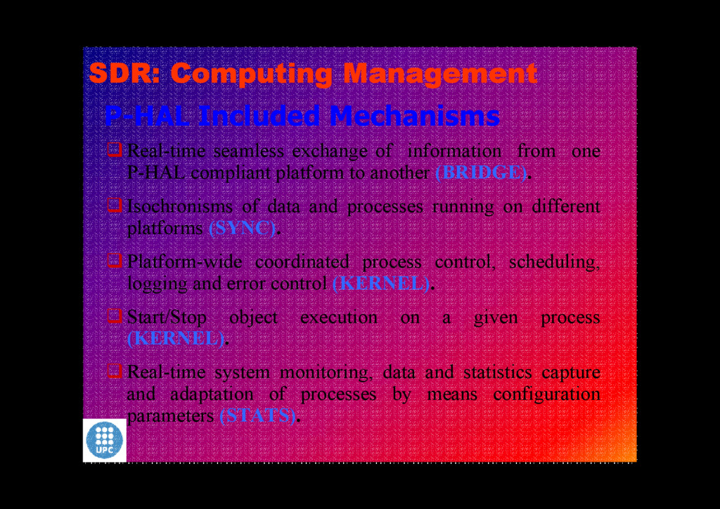
P-HAL compliant platform to another (BRIDGE). Isochronisms of data and processes running on different platforms (SYNC). Platform-wide coordinated process control, scheduling, logging and error control (KERNEL). Start/Stop object execution on a given process (KERNEL). Real-time system monitoring, data and statistics capture and adaptation of processes by means configuration parameters (STATS). SDR: Computing Management
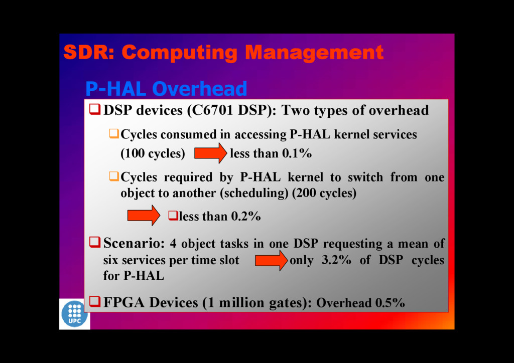
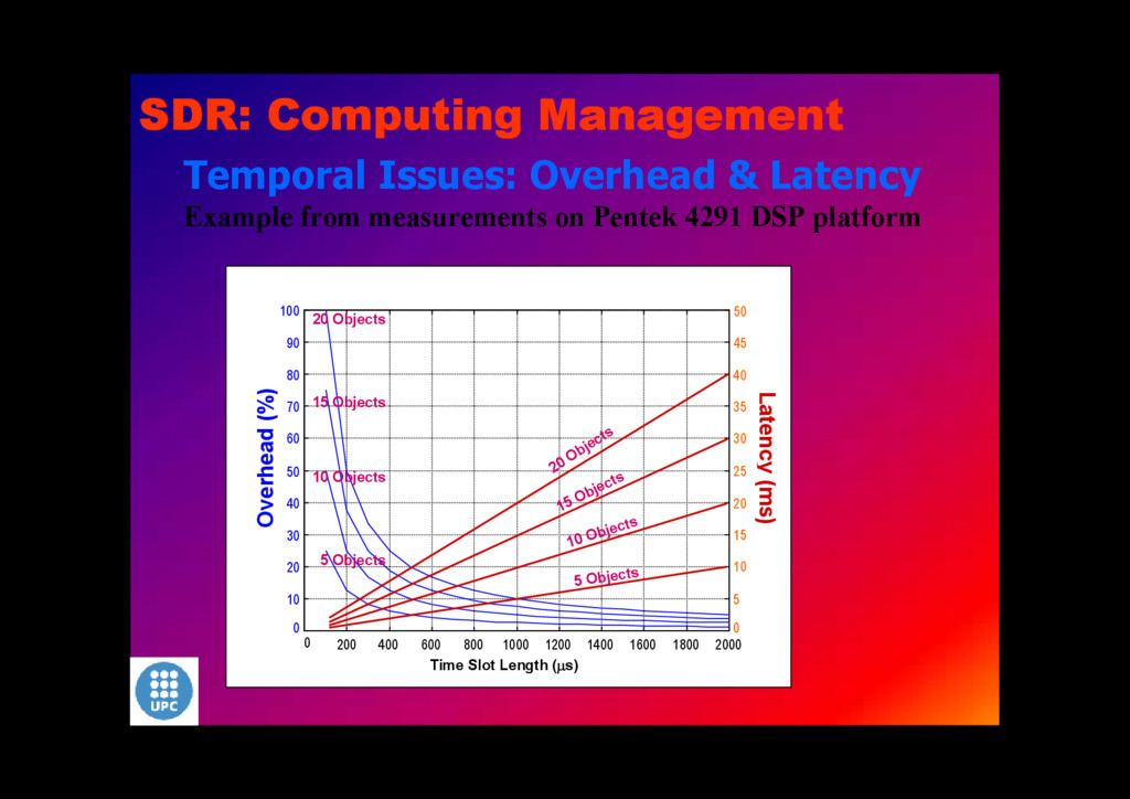
Cycles consumed in accessing P-HAL kernel services (100 cycles) less than 0.1% Cycles required by P-HAL kernel to switch from one object to another (scheduling) (200 cycles) less than 0.2% Scenario: 4 object tasks in one DSP requesting a mean of six services per time slot only 3.2% of DSP cycles for P-HAL FPGA Devices (1 million gates): Overhead 0.5% SDR: Computing Management