Phase Tracking at Low Signal-to-Noise Ratio And A Performance Comparison of a Parity-Code-Aided and a Pilot-Symbol-Assisted Approach Marie-Laure Boucheret IRIT-ENSEEIHT TéSA Mathieu Dervin(2), Nele Noels(1), Marc Moeneclaey(1) , Marie-Laure Boucheret(3) (1) TELIN Department, Ghent University (2) DRT Department, Alcatel Alenia Space (Toulouse) (3) IRIT ENSEEIHT TéSA, ENSEEIHT Toulouse This work has been partly performed in cooperation with the TELIN department of Ghent University, Belgium. It has been partly presented at the Ninth International Workshop on Signal Processing for Space Communications (SPSC 2006) in Noordwijk, The Netherlands, September 11-13, 2006
Problem formulation y Carrier synchronization at very low SNR y Objectives Proposed feedback synchronizers y Phase locked loop (PLL) structure y PLL with Non-Code-Aided (NCA) Operation y PLL with Single-Parity-Check Code-Aided (SPC-CA) Operation y PLL with Pilot-Bit-Aided (PBA) Operation Numerical Results for QPSK y Estimation of a constant carrier phase y Estimation of a time-varying carrier phase
Problem formulation y Carrier synchronization at very low SNR y Objectives Proposed feedback synchronizers y Phase locked loop (PLL) structure y PLL with Non-Code-Aided (NCA) Operation y PLL with Single-Parity-Check Code-Aided (SPC-CA) Operation y PLL with Pilot-Bit-Aided (PBA) Operation Numerical Results y Estimation of a constant carrier phase y Estimation of a time-varying carrier phase
formulation (1) Carrier synchronization at very low SNR Very powerful channel codes → Communications at very low SNR Correct decoding requires sufficient synchronization performance → Conventional synchronizers are not accurate enough → Carrier synchronization must be improved → New proposed synchronization schemes are based on the exploitation of some form of a priori information
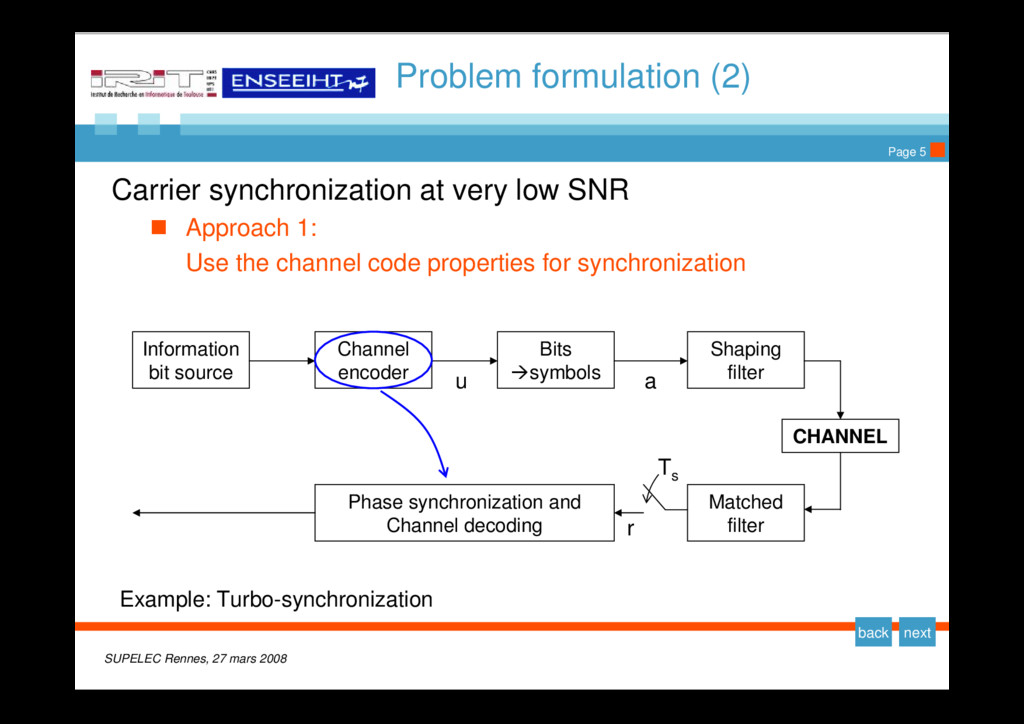
formulation (2) Carrier synchronization at very low SNR Approach 1: Use the channel code properties for synchronization Information bit source Channel encoder Bits Æsymbols Shaping filter CHANNEL Matched filter Phase synchronization and Channel decoding u a r T s Example: Turbo-synchronization
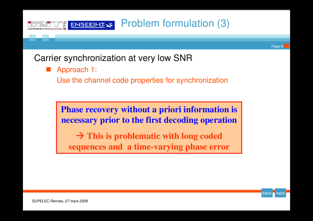
formulation (3) Carrier synchronization at very low SNR Approach 1: Use the channel code properties for synchronization Phase recovery without a priori information is necessary prior to the first decoding operation Æ This is problematic with long coded sequences and a time-varying phase error
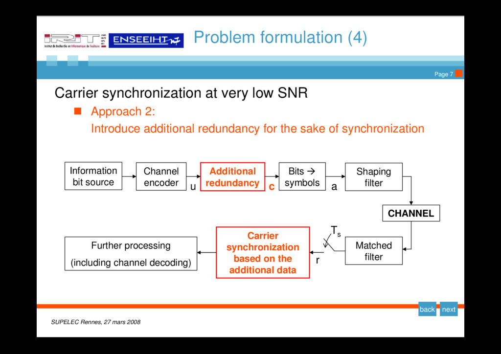
formulation (4) Carrier synchronization at very low SNR Approach 2: Introduce additional redundancy for the sake of synchronization Information bit source Channel encoder Bits Æ symbols Shaping filter CHANNEL Matched filter r T s Additional redundancy u c a Carrier synchronization based on the additional data Further processing (including channel decoding)
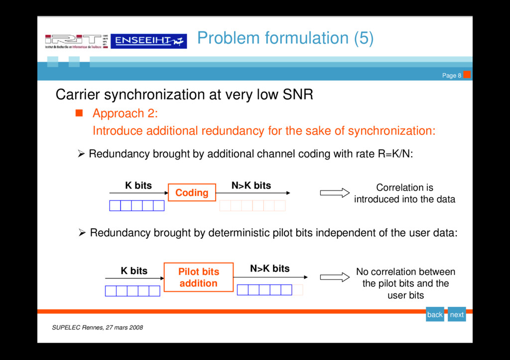
formulation (5) Carrier synchronization at very low SNR Approach 2: Introduce additional redundancy for the sake of synchronization: ¾ Redundancy brought by additional channel coding with rate R=K/N: Coding K bits N>K bits Correlation is introduced into the data ¾ Redundancy brought by deterministic pilot bits independent of the user data: No correlation between the pilot bits and the user bits Pilot bits addition K bits N>K bits
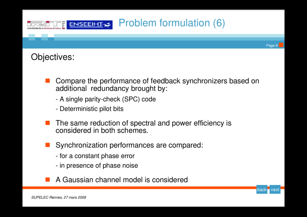
formulation (6) Objectives: Compare the performance of feedback synchronizers based on additional redundancy brought by: - A single parity-check (SPC) code - Deterministic pilot bits The same reduction of spectral and power efficiency is considered in both schemes. Synchronization performances are compared: - for a constant phase error - in presence of phase noise A Gaussian channel model is considered
Problem formulation y Carrier synchronization at very low SNR y Objectives Proposed feedback synchronizers y Phase locked loop (PLL) structure y PLL with Non-Code-Aided (NCA) Operation y PLL with Single-Parity-Check Code-Aided (SPC-CA) Operation y PLL with Pilot-Bit-Aided (PBA) Operation Numerical Results for QPSK y Estimation of a constant carrier phase y Estimation of a time-varying carrier phase
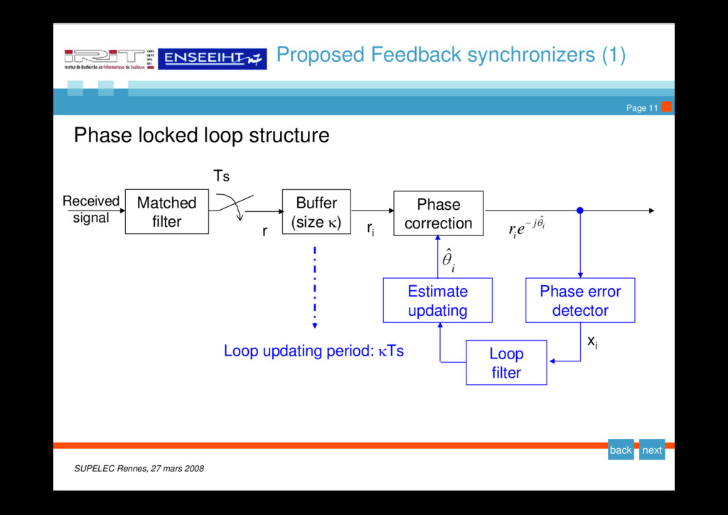
Feedback synchronizers (1) Phase locked loop structure Received signal Matched filter Phase error detector Loop filter Estimate updating Buffer (size κ) Phase correction r r i i j i e r θˆ − i θ ˆ x i Ts Loop updating period: κTs
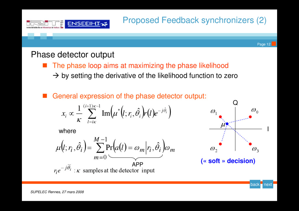
Feedback synchronizers (2) Phase detector output The phase loop aims at maximizing the phase likelihood Æ by setting the derivative of the likelihood function to zero General expression of the phase detector output: input detector at the samples : ~ κ θi j ie r − ( ) ( ) ( ) m M m i i m i i r l a r l ω θ ω θ μ ∑ − = = = 1 0 ˆ , Pr ˆ , ; where 0 ω 1 ω 2 ω 3 ω μ Q I (« soft » decision) APP ( ) ( ) ( ) ∑− + = − ∝ 1 ) 1 ( ˆ * ˆ , ; Im 1 κ κ θ θ μ κ i i l j i i i i e l r r l x
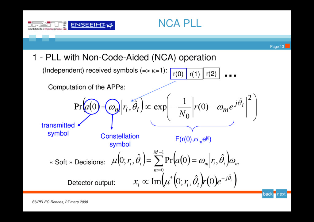
PLL 1 - PLL with Non-Code-Aided (NCA) operation (Independent) received symbols (=> κ=1): … « Soft » Decisions: ( ) ( ) ( ) m M m i i m i i r a r ω θ ω θ μ ∑ − = = = 1 0 ˆ , 0 Pr ˆ , ; 0 r(1) r(2) Detector output: ( ) ( ) ( ) i j i i i e r r x θ θ μ ˆ * 0 ˆ , ; 0 Im − ∝ r(0) Computation of the APPs: ( ) ( ) ⎟ ⎟ ⎠ ⎞ ⎜ ⎜ ⎝ ⎛ − − ∝ = 2 ˆ 0 ) 0 ( 1 exp ˆ , 0 Pr i j m i i m e r N r a θ ω θ ω transmitted symbol Constellation symbol F(r(0),ω m ejθ)
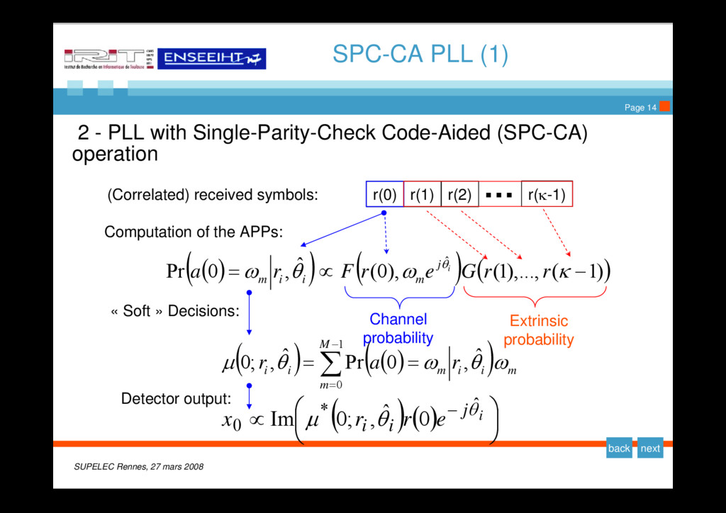
PLL (1) 2 - PLL with Single-Parity-Check Code-Aided (SPC-CA) operation (Correlated) received symbols: … « Soft » Decisions: ( ) ( ) ( ) m M m i i m i i r a r ω θ ω θ μ ∑ − = = = 1 0 ˆ , 0 Pr ˆ , ; 0 r(1) r(2) Detector output: ( ) ( ) ⎟ ⎠ ⎞ ⎜ ⎝ ⎛ ∝ − i j i i e r r x θ θ μ ˆ * 0 0 ˆ , ; 0 Im r(0) r(κ-1) Computation of the APPs: ( ) ( ) ( ) ( ) ) 1 ( ),..., 1 ( ), 0 ( ˆ , 0 Pr ˆ − ∝ = κ ω θ ω θ r r G e r F r a i j m i i m Channel probability Extrinsic probability
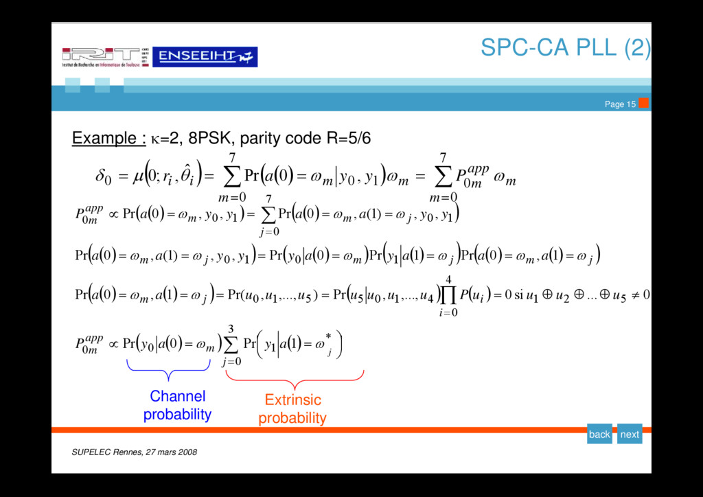
PLL (2) Example : κ=2, 8PSK, parity code R=5/6 ( ) ( ) ( ) m m app m m m m i i P y y a r ω ω ω θ μ δ ∑ ∑ = = = = = = 7 0 0 7 0 1 0 0 , 0 Pr ˆ , ; 0 ( ) ( ) ( ) ( ) ( ) ( ) ( ) ( ) ( ) ( ) ( ) ( ) ( ) ( ) ( ) ( ) ( ) ( ) ( ) ( ) ( ) ∑ ∏ ∑ = = = ⎟ ⎠ ⎞ ⎜ ⎝ ⎛ = = ∝ ≠ ⊕ ⊕ ⊕ = = = = = = = = = = = = = = = = ∝ 3 0 * 1 0 0 5 2 1 4 0 4 1 0 5 5 1 0 1 0 1 0 7 0 1 0 1 0 0 1 Pr 0 Pr 0 ... si 0 ,..., , Pr ) ,..., , Pr( 1 , 0 Pr 1 , 0 Pr 1 Pr 0 Pr , , ) 1 ( , 0 Pr , , ) 1 ( , 0 Pr , , 0 Pr j m app m i i j m j m j m j m j j m m app m j a y a y P u u u u P u u u u u u u a a a a a y a y y y a a y y a a y y a P ω ω ω ω ω ω ω ω ω ω ω ω ω Extrinsic probability Channel probability
3 - PLL with Pilot-Bit-Aided (PBA) operation (Non correlated) received symbols: … r(1) r (κ-2) r(0) r(κ-1) Computation of the APPs: ( ) ( ) ( ) i j m i i m e l r F r l a θ ω θ ω ˆ ), ( ˆ , Pr ∝ = L=0,…, κ-2: ( ) ( ) ( ) ⎪ ⎩ ⎪ ⎨ ⎧ ∝ = otherwise 0 bit pilot the involving ω for ), 0 ( ˆ , 0 Pr m ˆ i j m i i m e r F r a θ ω θ ω L=κ-1:
Problem formulation y Carrier synchronization at very low SNR y Objectives Proposed feedback synchronizers y Phase locked loop (PLL) structure y PLL with Non-Code-Aided (NCA) Operation y PLL with Single-Parity-Check Code-Aided (SPC-CA) Operation y PLL with Pilot-Bit-Aided (PBA) Operation Numerical Results for QPSK y Estimation of a constant carrier phase y Estimation of a time-varying carrier phase
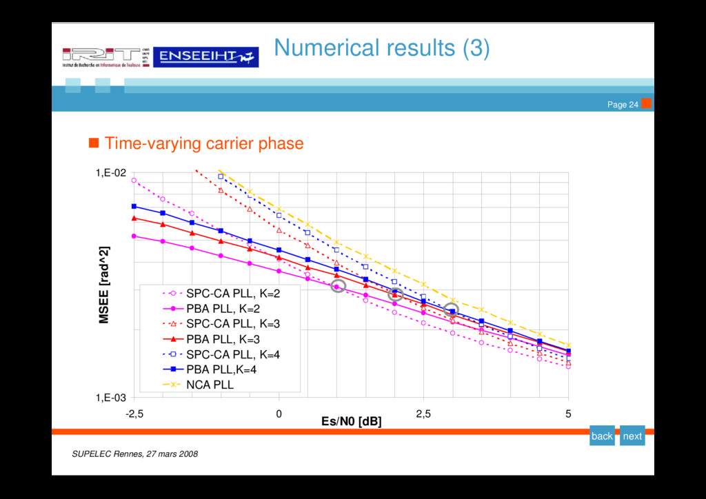
results (2) Time-varying carrier phase ¾ QPSK modulation (gray mapping) ¾ Phase noise model satisfying the spectral template defined in DVB-S2 standard ¾ Second order PLL with a damping factor of 0.707 ¾ An optimal loop bandwidth allows to minimize the mean square estimation error (MMSE) in presence of phase noise
results (4) Conclusions ¾ Both algorithms exploiting data overhead outperform the non-code aided scheme ¾ For a given overhead ratio: The SPC-code-aided PLL performs better at moderate to high SNR The Pilot-bit-aided PLL performs better at low SNR ¾ For a given SNR, the synchronizer performance of both systems improves with decreasing spectral efficiency.
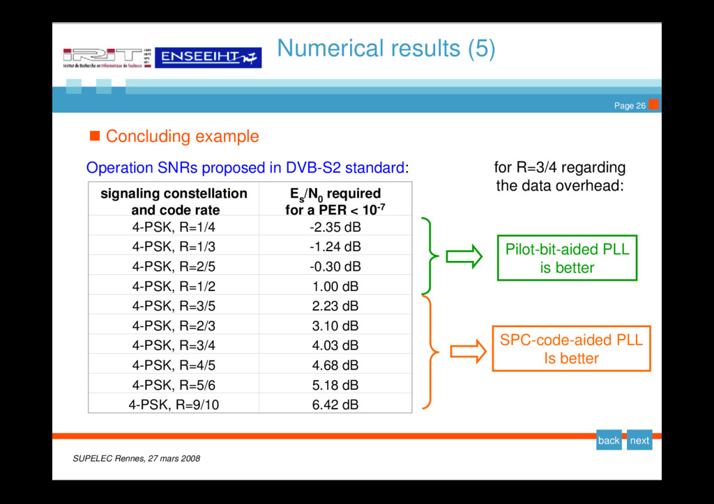
results (5) Concluding example signaling constellation and code rate E s /N 0 required for a PER < 10-7 4-PSK, R=1/4 -2.35 dB 4-PSK, R=1/3 -1.24 dB 4-PSK, R=2/5 -0.30 dB 4-PSK, R=1/2 1.00 dB 4-PSK, R=3/5 2.23 dB 4-PSK, R=2/3 3.10 dB 4-PSK, R=3/4 4.03 dB 4-PSK, R=4/5 4.68 dB 4-PSK, R=5/6 5.18 dB 4-PSK, R=9/10 6.42 dB Operation SNRs proposed in DVB-S2 standard: SPC-code-aided PLL Is better Pilot-bit-aided PLL is better for R=3/4 regarding the data overhead: