Upgrade to Pro — share decks privately, control downloads, hide ads and more …

Stéphane Lecomte - Models driven co-design methodology for SDR systems

SCEE Team
September 24, 2009

Stéphane Lecomte - Models driven co-design methodology for SDR systems

SCEE Team

September 24, 2009
Tweet

More Decks by SCEE Team

Other Decks in Research

Transcript

  1. Séminaire Supélec/SCEE Models driven co-design methodology for SDR systems Directeur

    de thèse PALICOT Jacques Co-directeur LERAY Pierre Encadrant industriel GUILLOUARD Samuel LECOMTE Stéphane
  2. Outline Context Objectives of thesis Definitions/Vocabulary MDA co-design methodology :

    MOPCOM MDA tools Experiments 2 09/24/2009 Experiments Conclusion
  3. Outline Context Objectives of thesis Definitions/Vocabulary MDA Co-design Methodology :

    MOPCOM MDA tools Experiments 3 09/24/2009 Experiments Conclusion
  4. Challenge Design of real time embedded systems More and more

    complex systems Heterogeneous systems Technology of digital chip improving quickly Integrating a system into one chip SoC : System on Chip => ASIC* SoPC : System on Programmable Component => FPGA** Shorter and shorter Time-to-Market 4 09/24/2009 * ASIC : Application-Specific Integrated Circuit **FPGA : Field Programmable Gate Array
  5. State of the art Today the co-design methodologies do not

    progress as quickly as the technology Rupture of design process Different process For hardware For embedded software Specific tools Requirements Analysis Specification of system Software/hardware partitioning Nb gates (millions) 100 Specific tools For hardware design (EDA tools) For embedded software Integration and Validation Too long Too many difficulties 5 09/24/2009 Software/hardware partitioning Embedded Software development process Hardware development process Co-simulation Co-verification time 95 2001 2007 GAP (around x3) 1 10 100
  6. Solutions Problems Solutions Increasing complexity, Decreasing Time-to-Market High level approach

    to increase productivity Portability, functionality/architecture independence Component-based approach Reuse Common formalism for system/ Communications between teams Common formalism for system/ software and hardware engineer Obsolescence Capitalize knowledge and experience Quality of process Process formalization Traceability and test improvement 6 09/24/2009 Use the same design process and tools for hardware and embedded software development
  7. Outline Context Objectives of thesis Definitions/Vocabulary MDA Co-design Methodology :

    MOPCOM MDA tools Experiments 7 09/24/2009 Experiments Conclusion
  8. Objectives of thesis Formalization of a new development process based

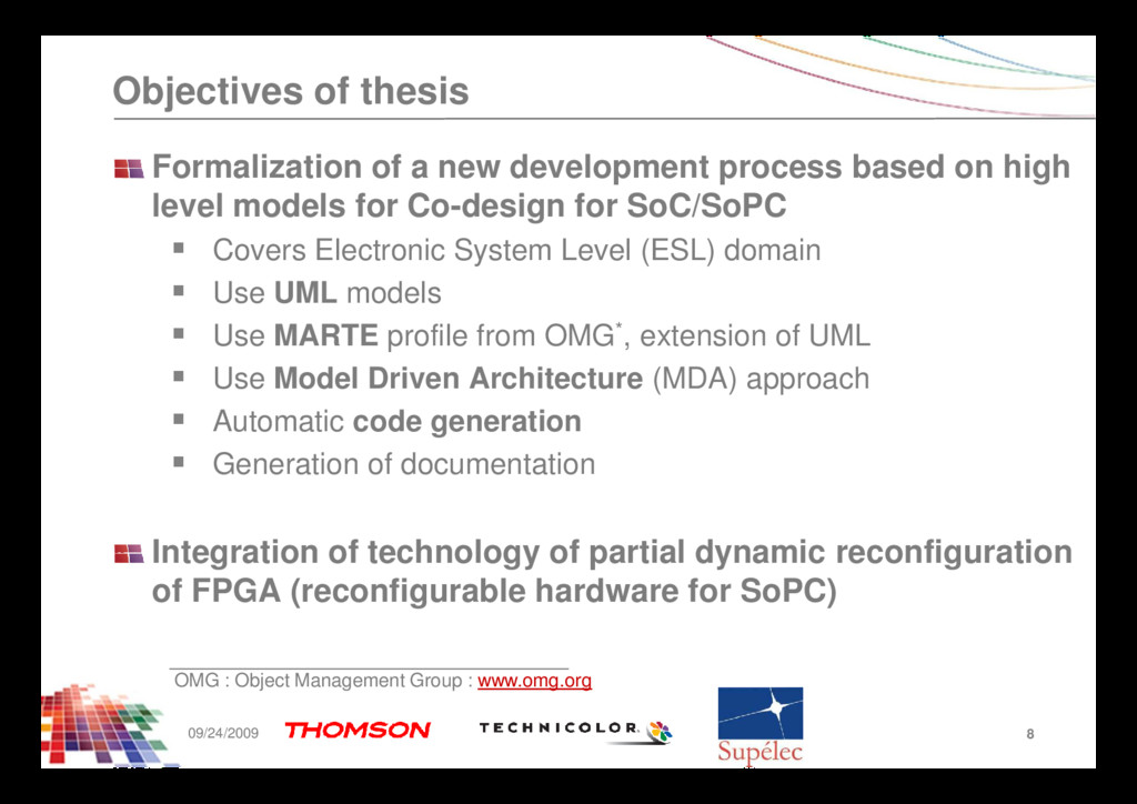
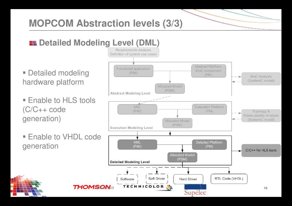
    on high level models for Co-design for SoC/SoPC Covers Electronic System Level (ESL) domain Use UML models Use MARTE profile from OMG*, extension of UML Use Model Driven Architecture (MDA) approach Automatic code generation Generation of documentation Integration of technology of partial dynamic reconfiguration of FPGA (reconfigurable hardware for SoPC) 8 09/24/2009 OMG : Object Management Group : www.omg.org
  9. Outline Context Objectives of thesis Definitions/Vocabulary MDA Co-design Methodology :

    MOPCOM MDA tools Experiments 9 09/24/2009 Experiments Conclusion
  10. Model Driven Architecture (MDA) Based on model transformations to formalize

    and to automate the design process MDA Process based on several model types Platform Independent Model (PIM) Platform Model (PM) Platform Specific Model (PSM) Use the modeling language : Unified Modeling Language Standardized language by the OMG Graphical & annoted language for modeling high level design approach UML describes structural and behaviour aspects of the systems 10 09/24/2009
  11. Outline Context Objectives of thesis Definitions/Vocabulary MDA Co-design Methodology :

    MOPCOM MDA tools Experiments 11 09/24/2009 Experiments Conclusion
  12. A Design Process based on UML Profiles UML is a

    unified language but not a methodology How to design hardware with UML ? Integration with system and software processes UML extension to RTE systems MARTE (Modeling and Analysis of Real Time and Embedded systems) Profile Modeling time constraints Modeling Hardware Modeling Allocation Performances analysis Huge set of concepts No methodology to support activity based on MARTE 13 09/24/2009
  13. MOPCOM Abstraction levels (1/3) Abstract Modeling Level (AML) Modeling of

    high level of abstraction Validation of 14 09/24/2009 Validation of functional architecture and behavior
  14. MOPCOM Abstraction levels (2/3) Execution Modeling Level (EML) Modeling the

    topology of hardware platform Add information of 15 09/24/2009 Add information of time constraints Dedicated to architecture exploration
  15. MOPCOM Abstraction levels (3/3) Detailed Modeling Level (DML) Detailed modeling

    hardware platform Enable to HLS tools 16 09/24/2009 Enable to HLS tools (C/C++ code generation) Enable to VHDL code generation
  16. MOPCOM flow Three levels of modeling Each level use MDA

    approach Modeling with UML and MARTE Formalization of process A meta-model describes the process Associated modeling constraints for each level Associated modeling constraints for each level MOPCOM Profile Add concepts that do not exist in UML and MARTE Iterative design process 17 09/24/2009
  17. Outline Context Objectives of thesis Definitions/Vocabulary MDA Co-design Methodology :

    MOPCOM Tools environment in MOPCOM Experiments 18 09/24/2009 Experiments Conclusion
  18. MDA tools Kermeta (metamodeling) Process (methodology) Methodological Rules (architecture, functional,

    allocation) UML/MARTE Metamodel Open Source Capitalization 19 09/24/2009 Tools instanciation Scripts Java/EMF (transformation & generation) Papyrus (modeling) User entry : system specification Generated code
  19. MOPCOM tools Kermeta (metamodeling) Process (methodology) Methodological Rules (architecture, functional,

    allocation) UML/MARTE Metamodel Open Source Capitalization 20 09/24/2009 Rhapsody (modeling) MDWorkbench (transformation & generation) MOPCOM Tools instanciation MDWorkbench scripts Generated code (RTL, C, C++) User entry : system specification
  20. Code generator integrated in Rhapsody Seamless integration in Rhapsody-in-C++ 7.5

    Generation from Statecharts Definition of VHDL OMD for Application & Platform VHDL Configuration DML, Application & Platform Packages 21 09/24/2009 VHDL properties Logs & Build Links with EDA tools Edition of VHDL code External Generator based on RulesComposer & RulesPlayer MARTE & MOPCOM Profiles Hardware Libraries & Types
  21. Outline Context Objectives of thesis Definitions/Vocabulary MDA Co-design Methodology :

    MOPCOM Tools environment in MOPCOM Experiments 22 09/24/2009 Experiments Conclusion
  22. Test applications Goal Validation of MOPCOM co-design methodology Validation the

    MDA tools instance in MOPCOM Evaluation Comparison with traditional co-design flow Profits (time and cost) Portability of MOPCOM methodology in others context Reusability of process with others MDA tools 23 09/24/2009
  23. Supelec experiment for MOPCOM Limited SDR system Constellation Constellation Constellation

    Constellation Constellation Constellation Constellation Constellation 24 09/24/2009 Constellation Constellation Constellation Constellation QPSK 16-QAM roll-off=0.22 roll-off=0.015 Constellation Constellation Constellation Constellation QPSK 16-QAM roll-off=0.22 roll-off=0.015
  24. Platform Model DML Model Used to manage the partial reconfiguration

    26 09/24/2009 Identify this PLD resource to a reconfigurable resource with a specific tag
  25. SystemC model Modeling level SystemC OSCI Untimed Functional Transaction Level

    Modeling Programmer's View Timed Functional PV + Timing Cycle Accurate Bus Accurate Cycle Callable Register Transfer Level RTL SystemC RTL Programmer’s View (untimed) Equivalence with AML 28 09/24/2009
  26. Outline Context Objectives of thesis Definitions MDA Co-design Methodology :

    MOPCOM Tools environment in MOPCOM Experiments 29 09/24/2009 Experiments Conclusion
  27. Conclusion Feedback Portability of methodology is difficult UML tools makes

    specific/proprietary model interpretation Reuse of models is difficult Existing code generators are not complete First co-design methodology using MARTE profile for modeling RTE system RTE system Same process for design hardware and software Future works Code generator fully integrated inside the modeling tool Updating the code generators Use the methodology in others domains 30 09/24/2009
  28. Acknowledgement Partners of MoPCoM SoC/SoPC project* Thalès (Airborne Systems) Thomson

    (Corporate Research) Sodius ENSIETA Lab-STICC (UBS) INIRIA (Triskell team) Supelec (SCEE team) 31 09/24/2009 MOPCOM web site : www.mopcom.fr