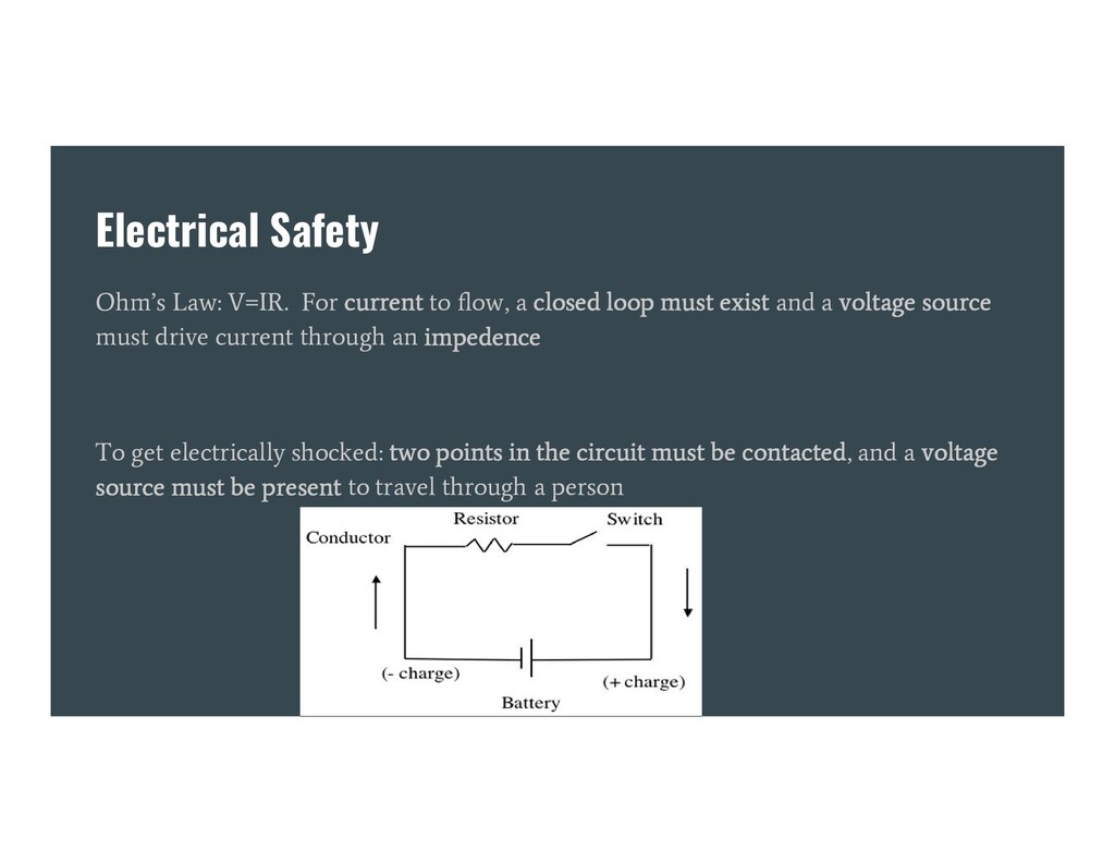
closed loop must exist and a voltage source must drive current through an impedence To get electrically shocked: two points in the circuit must be contacted, and a voltage source must be present to travel through a person
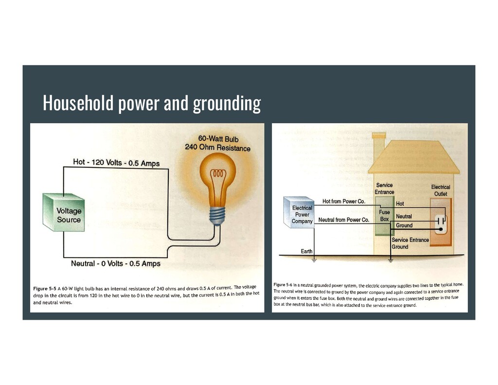
safety, most OR power is ISOLATED, not grounded and technically ungrounded In a household system, the grounding wire limits the severity of a potential shock by providing a low resistance pathway to ground. It doesn’t prevent a shock, just limits its severity.
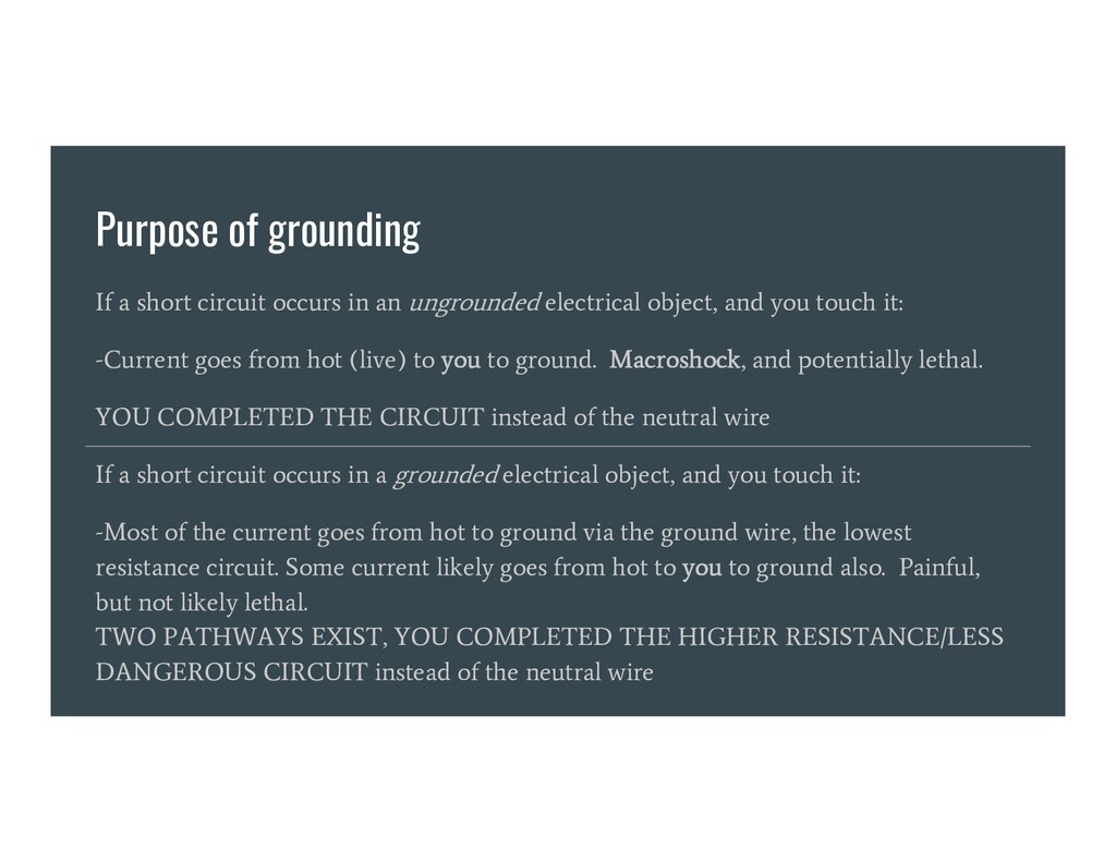
ungrounded electrical object, and you touch it: -Current goes from hot (live) to you to ground. Macroshock, and potentially lethal. YOU COMPLETED THE CIRCUIT instead of the neutral wire If a short circuit occurs in a grounded electrical object, and you touch it: -Most of the current goes from hot to ground via the ground wire, the lowest resistance circuit. Some current likely goes from hot to you to ground also. Painful, but not likely lethal. TWO PATHWAYS EXIST, YOU COMPLETED THE HIGHER RESISTANCE/LESS DANGEROUS CIRCUIT instead of the neutral wire
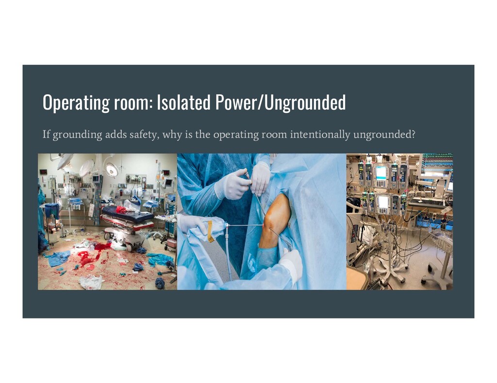
and isolated because: -Cables -Power cords -Electronic devices -Puddles of saline or blood on the floor Make the operating room an electrically hazardous environment 40% of electrical accidents in hospitals occur in the operating room
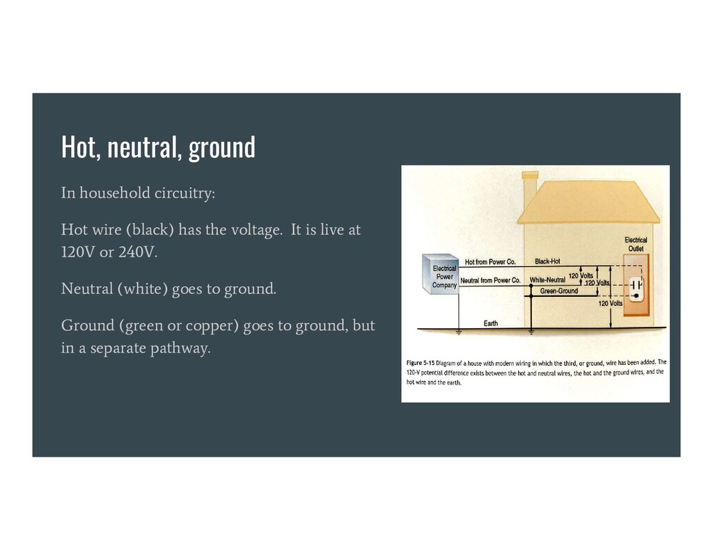
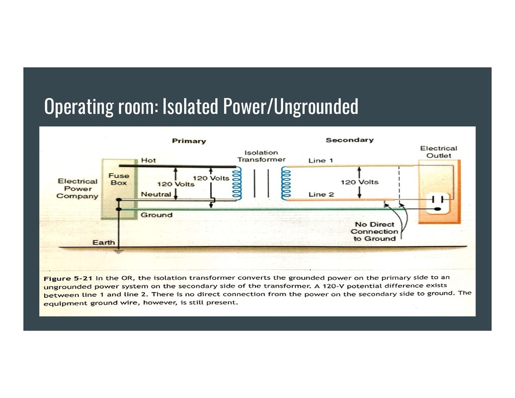
isolation transformer is used to separate operating room power from the grounded power source -A 120V potential difference then exists only between the two wires of the isolated power system. -This is different from household circuitry, where the voltage difference exists between hot and ground. Neutral is just another ground on another wire - they both go to the same place. -No circuit exists between the ground and either of the isolated power lines.
two holes in the isolated power system. You have to touch both contacts to be shocked. You’re not part of the equation otherwise -Faulty equipment, even if short-circuited, will not usually trip the circuit breaker. This is important, as otherwise the anesthesia machine, lights, electrocautery etc, would shut off. -If a short circuit or fault develops in a grounded piece of equipment in an isolated power system, the isolated power becomes grounded power. Two faults are needed to create a hazard instead of just one. Electrical equipment, however, should ALWAYS be grounded in the OR. This is part of the total electrical safety program.
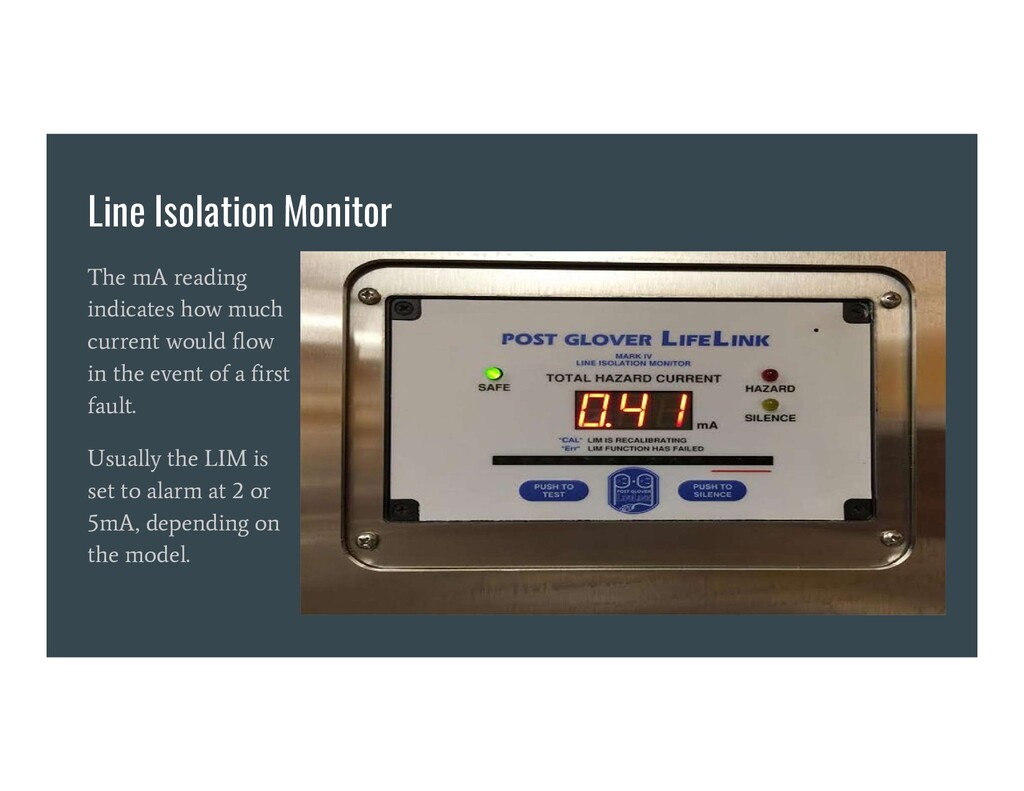
isolated power system. If faulty equipment is connected, it changes to grounded power – this is important to be able to monitor. -If it’s not monitored, how could you know there was a fault or it was now grounded power? How would you know the system was working? -If LIM alarm goes off in the OR – it doesn’t mean there’s a hazard, rather it means the system is no longer isolated from ground, maybe due to a fault. Needs a second fault for danger. Exercise caution, contact biomed, but usually no need to abort the case.
injured in two ways: -Electrical disruption of normal electrical function: muscle contraction, brain function alteration, respiratory paralysis, dysrhythmia -Electrical energy dissipation through body tissue, increasing temperature and burning
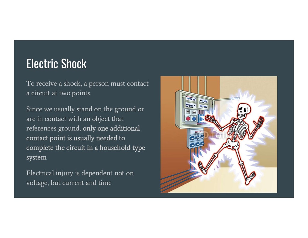
a circuit at two points. Since we usually stand on the ground or are in contact with an object that references ground, only one additional contact point is usually needed to complete the circuit in a household-type system Electrical injury is dependent not on voltage, but current and time
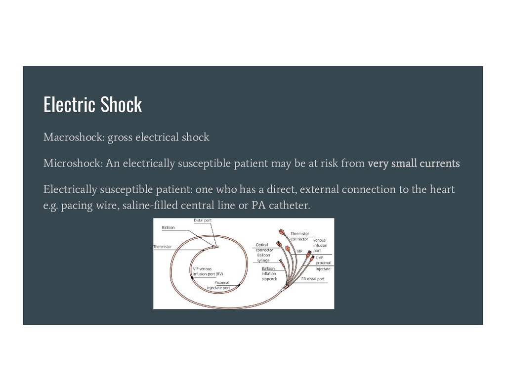
patient may be at risk from very small currents Electrically susceptible patient: one who has a direct, external connection to the heart e.g. pacing wire, saline-filled central line or PA catheter.
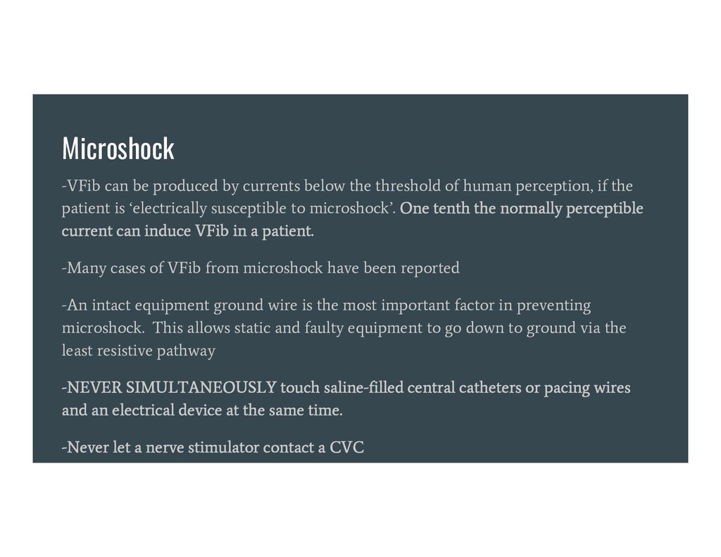
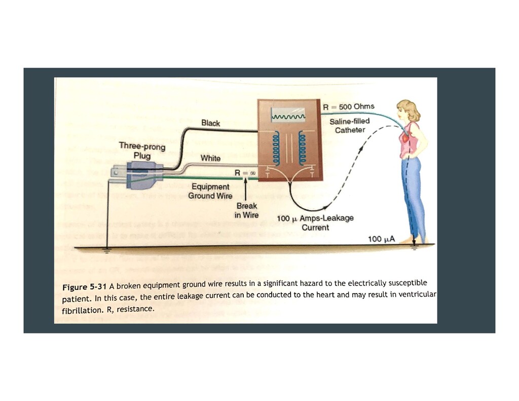
of human perception, if the patient is ‘electrically susceptible to microshock’. One tenth the normally perceptible current can induce VFib in a patient. -Many cases of VFib from microshock have been reported -An intact equipment ground wire is the most important factor in preventing microshock. This allows static and faulty equipment to go down to ground via the least resistive pathway -NEVER SIMULTANEOUSLY touch saline-filled central catheters or pacing wires and an electrical device at the same time. -Never let a nerve stimulator contact a CVC
Professor William Bovie. Bovie = ESU. - Hastened the removal of explosive anesthetic agents from the OR - “Bovie” interferes with pulse ox, pacemakers, ECG signal, CO computers - ESU generates freq. of 500,000 - 1million Hz of current to create heat energy. - Energy is concentrating at the tip of the “bovie pencil” to cut or coagulate. Low tissue penetration and doesn’t excite contractile cells -Bipolar ESU: current only flows from the tips of forceps. No need for a dispersion pad unless monopolar ESU also used.
the heart, with central venous catheters -ESU cannot be safely operated unless the energy is properly routed from the tip, through the patient, and out the back to the unit. The energy used for cutting or coag passes through the patient to a dispersive electrode of large surface area that returns the energy safely to the ESU. -Bovie pads are not grounding pads! They do not ground the patient! They are dispersion pads. If they grounded the patient they would kill the patient!
Bovie, AICD functions should be disabled, especially for surgeries on or near the thorax. This usually means placing a magnet over the device. -The risk is the AICD interprets ESU as Vfib, sends a defib current to the heart, and patient becomes asystolic or in actual VFib -Magnets are NOT magical. They flip switches on AICDs and pacemakers. Most magnets disable AICDs. -With pacemakers, magnets flip switches that… do other things. Usually the mode goes to VOO at a set rate – only originally designed as a battery check. -The only way to know what a magnet does to a pacemaker is by having it interrogated and asking the rep!
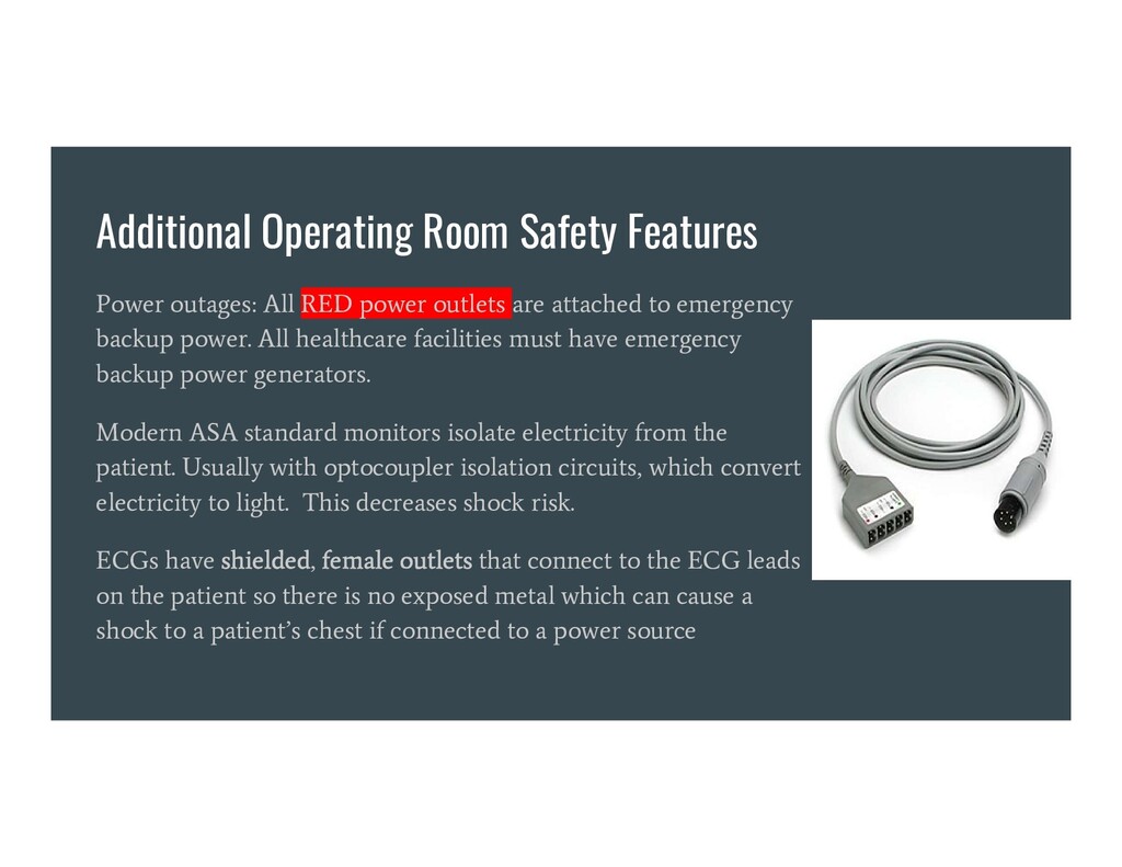
outlets are attached to emergency backup power. All healthcare facilities must have emergency backup power generators. Modern ASA standard monitors isolate electricity from the patient. Usually with optocoupler isolation circuits, which convert electricity to light. This decreases shock risk. ECGs have shielded, female outlets that connect to the ECG leads on the patient so there is no exposed metal which can cause a shock to a patient’s chest if connected to a power source
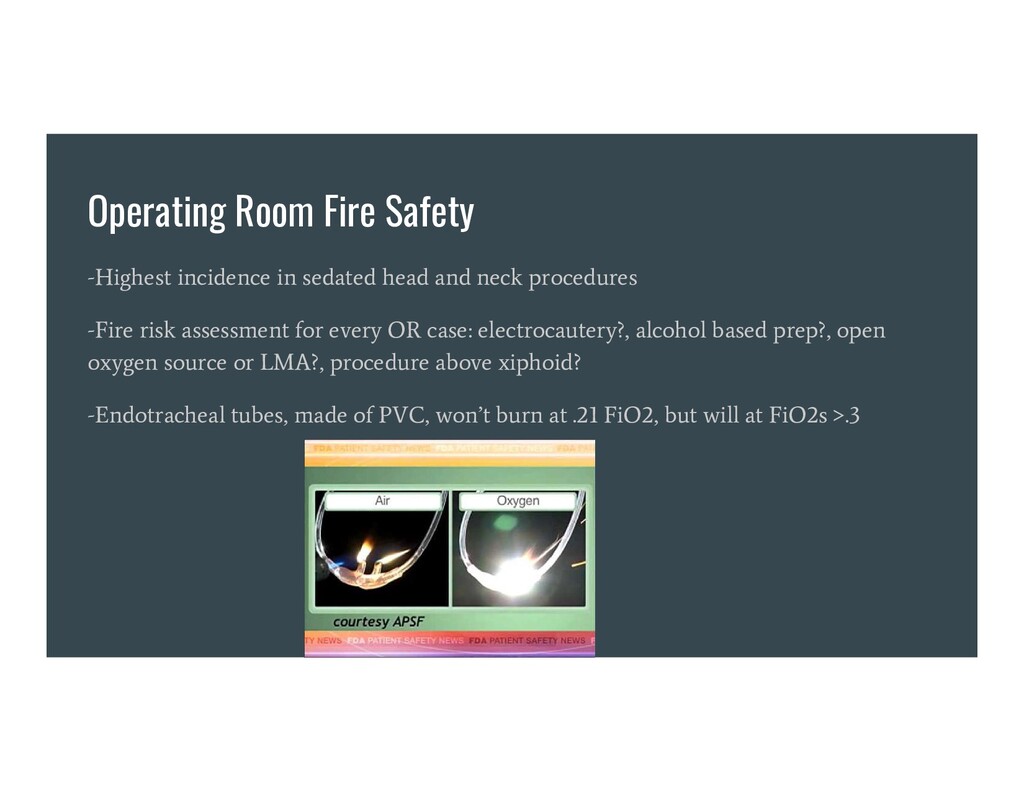
neck procedures -Fire risk assessment for every OR case: electrocautery?, alcohol based prep?, open oxygen source or LMA?, procedure above xiphoid? -Endotracheal tubes, made of PVC, won’t burn at .21 FiO2, but will at FiO2s >.3
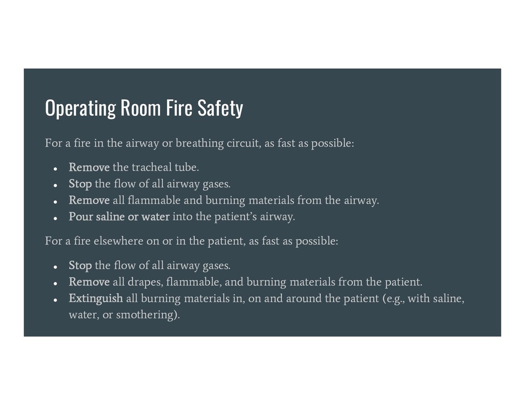
or breathing circuit, as fast as possible: • Remove the tracheal tube. • Stop the flow of all airway gases. • Remove all flammable and burning materials from the airway. • Pour saline or water into the patient’s airway. For a fire elsewhere on or in the patient, as fast as possible: • Stop the flow of all airway gases. • Remove all drapes, flammable, and burning materials from the patient. • Extinguish all burning materials in, on and around the patient (e.g., with saline, water, or smothering).
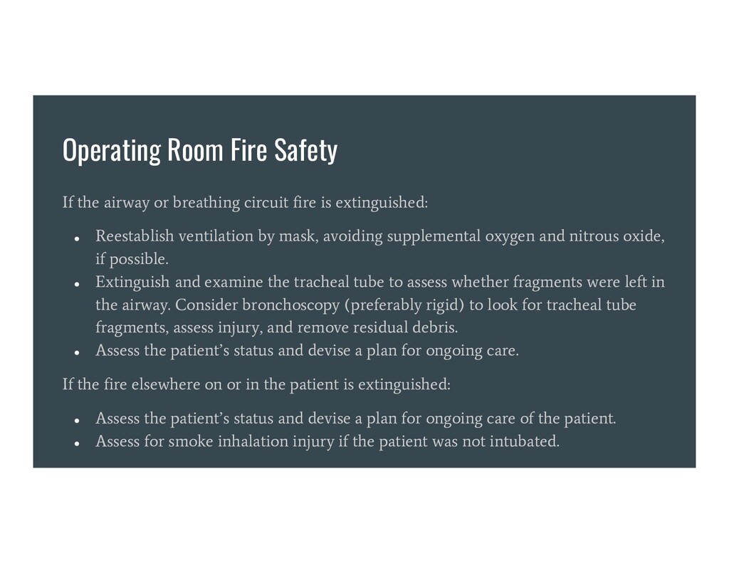
fire is extinguished: • Reestablish ventilation by mask, avoiding supplemental oxygen and nitrous oxide, if possible. • Extinguish and examine the tracheal tube to assess whether fragments were left in the airway. Consider bronchoscopy (preferably rigid) to look for tracheal tube fragments, assess injury, and remove residual debris. • Assess the patient’s status and devise a plan for ongoing care. If the fire elsewhere on or in the patient is extinguished: • Assess the patient’s status and devise a plan for ongoing care of the patient. • Assess for smoke inhalation injury if the patient was not intubated.
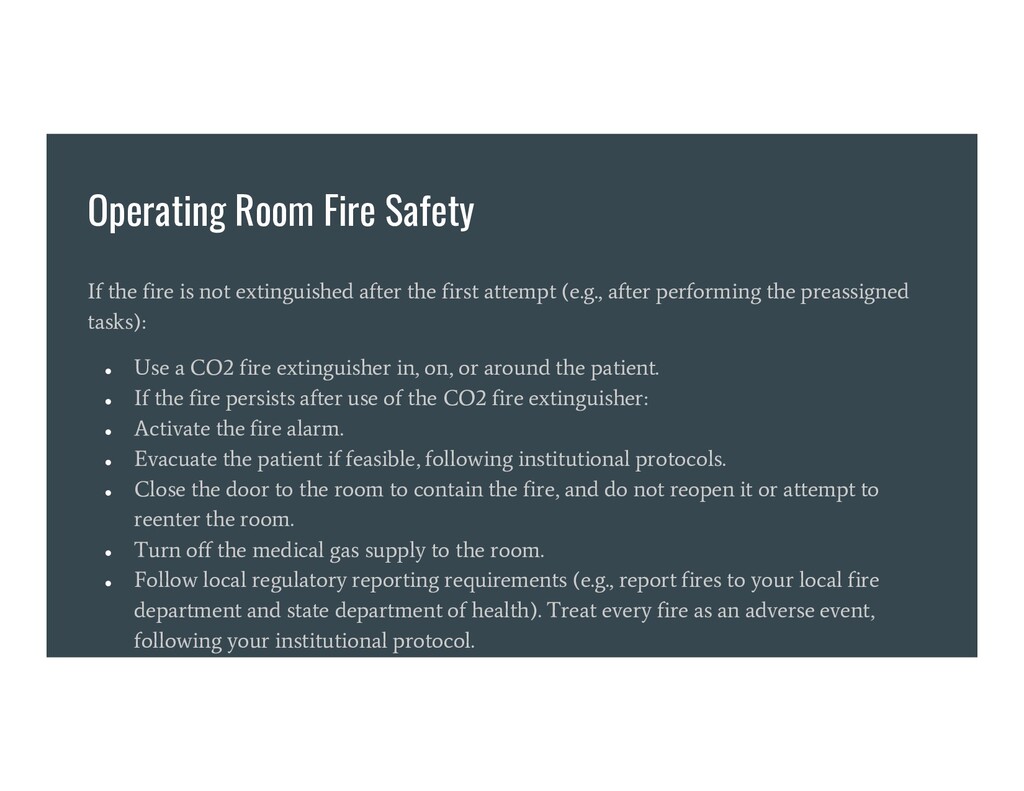
after the first attempt (e.g., after performing the preassigned tasks): • Use a CO2 fire extinguisher in, on, or around the patient. • If the fire persists after use of the CO2 fire extinguisher: • Activate the fire alarm. • Evacuate the patient if feasible, following institutional protocols. • Close the door to the room to contain the fire, and do not reopen it or attempt to reenter the room. • Turn off the medical gas supply to the room. • Follow local regulatory reporting requirements (e.g., report fires to your local fire department and state department of health). Treat every fire as an adverse event, following your institutional protocol.
Most machines will register an alarm at 21% O2 - In the circle breathing circuit, the most useful measurement site is within the breathing circuit, near the inhalation check valve - Causes of hypoxic mixtures: unrecognized nitrous oxide flow meter control knob mistaken for air O2 demand exceeds supply in closed circuit anesthesia oxygen supply pressure falls oxygen source disconnection gas from O2 source is not pure O2
shutoff (“fail safe”) If running a nitrous/oxygen mixture and the O2 supply or canister pressure falls, nitrous will be shut off. Doesn’t work with any gases but nitrous oxide. Test by closing O2 canister, running a nitrous/O2 mixture, then disconnecting the O2 pipeline supply. Nitrous should auto-shut off 3. Oxygen supply pressure failure alarm An audible alarm in case of O2 supply pressure loss 4. Single oxygen flow control knob Certain vintage machines have separate knobs for administering high and low oxygen flow meters. This is inherently dangerous. A single O2 flow knob is safest
knob A large diameter, differently groove “fluted” type knob, different in feeling than other knobs. Facilitates locating the oxygen knob whether color blind or low ambient lighting. Feel them with eyes closed next time you’re in the OR. 6) Oxygen flow meter at extreme right (U.S.) The standardized location increases safety. 7) Central gas supply pressure gauges Measures pressure of O2, N2O, and Air from each supply line. Verifies that hoses are connected and pressurized, and used to identify failures.
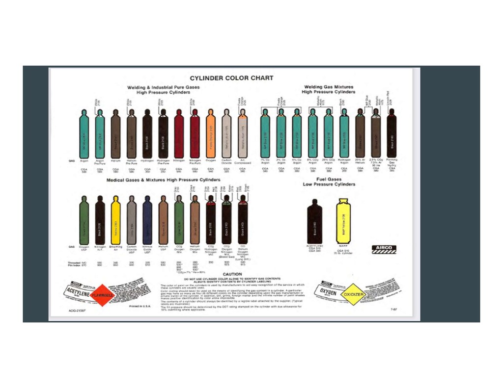
canisters, supply lines, & control knobs Uniquely colored for each gas. US: green O2, blue Nitrous, yellow Air. Different countries use different colors - be aware! Tanks have varied coloration too. Grey is CO2, Black is nitrogen. 9. Oxygen/nitrous oxide ratio monitor/controller Senses the ratio of flow meter settings for nitrous oxide and oxygen and issues an alarm when the ratio is unsafe. A ratio controller assures that flows cannot be adjusted outside a specific range of ratios. Specifically, pure nitrous oxide cannot be administered. Usually this is 70% nitrous 30% O2 max. Test by turning up nitrous flow, then decreasing O2 flow.
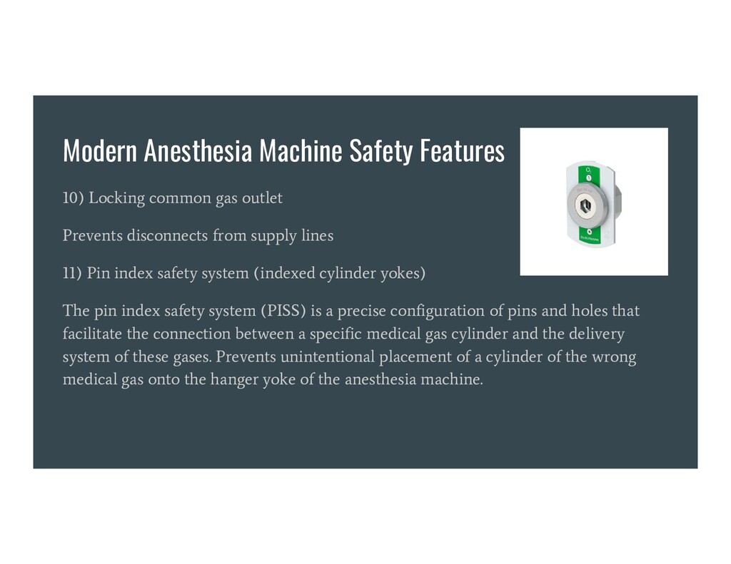
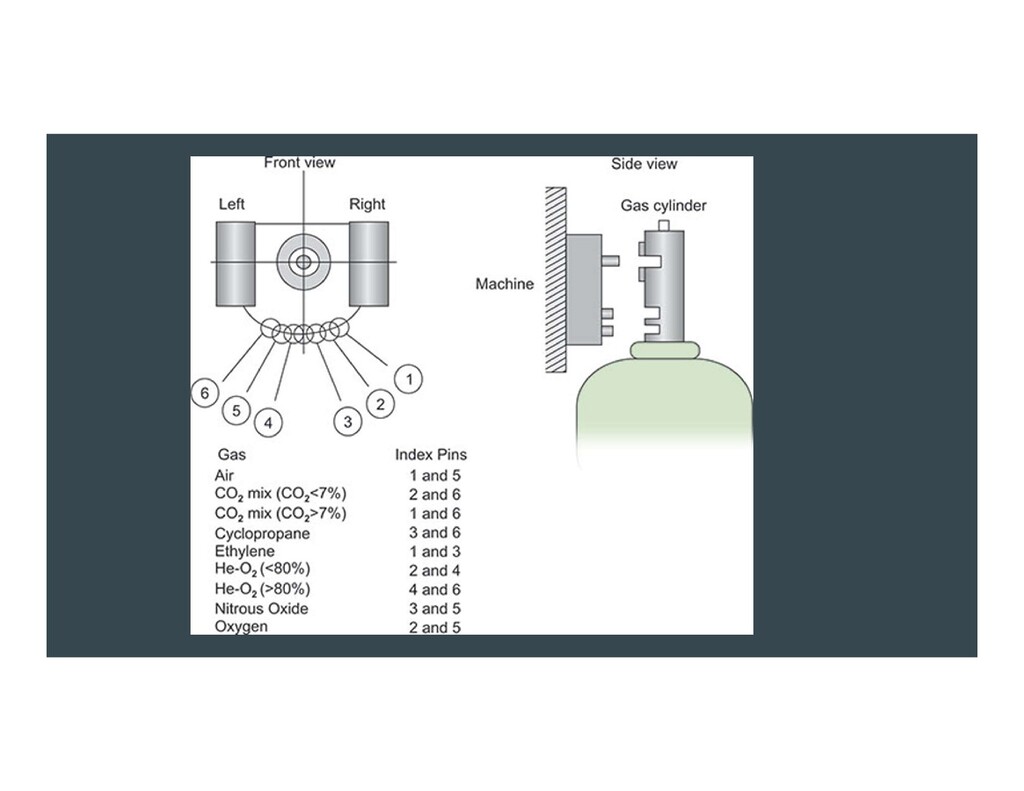
Prevents disconnects from supply lines 11) Pin index safety system (indexed cylinder yokes) The pin index safety system (PISS) is a precise configuration of pins and holes that facilitate the connection between a specific medical gas cylinder and the delivery system of these gases. Prevents unintentional placement of a cylinder of the wrong medical gas onto the hanger yoke of the anesthesia machine.
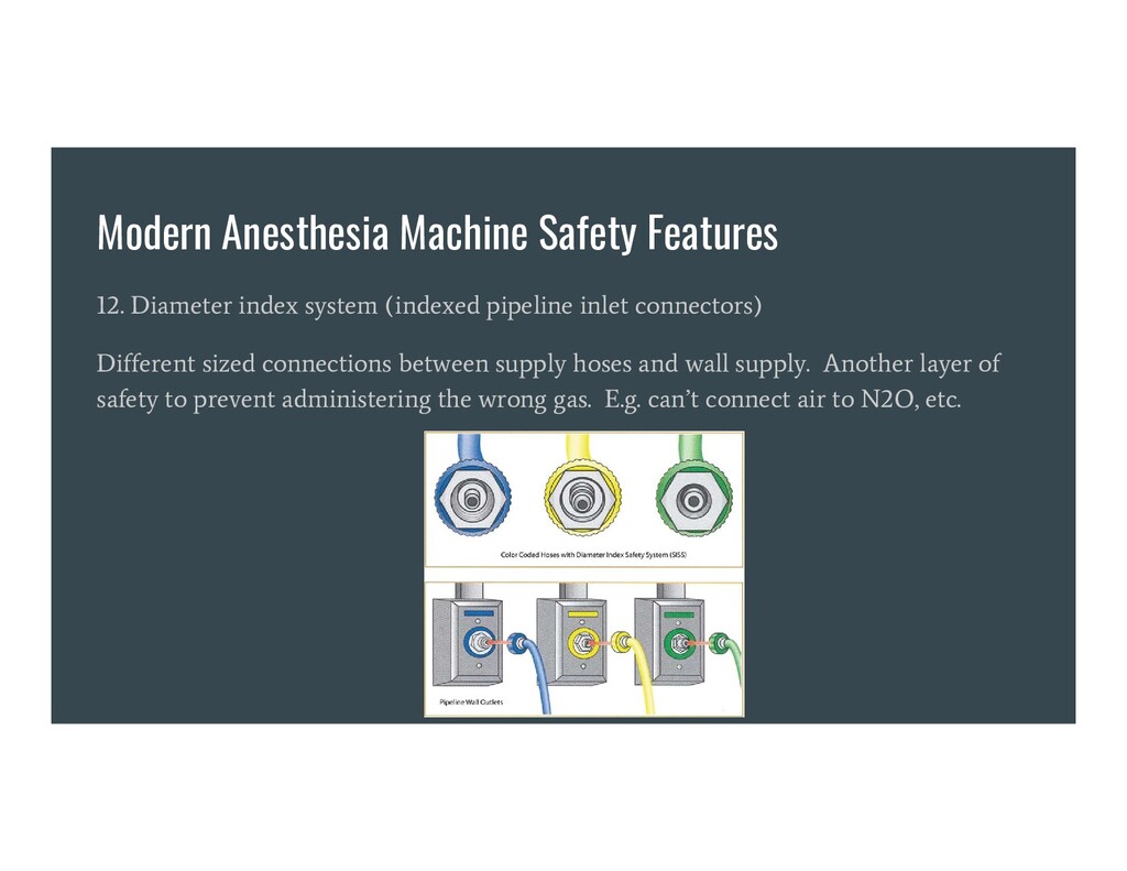
pipeline inlet connectors) Different sized connections between supply hoses and wall supply. Another layer of safety to prevent administering the wrong gas. E.g. can’t connect air to N2O, etc.
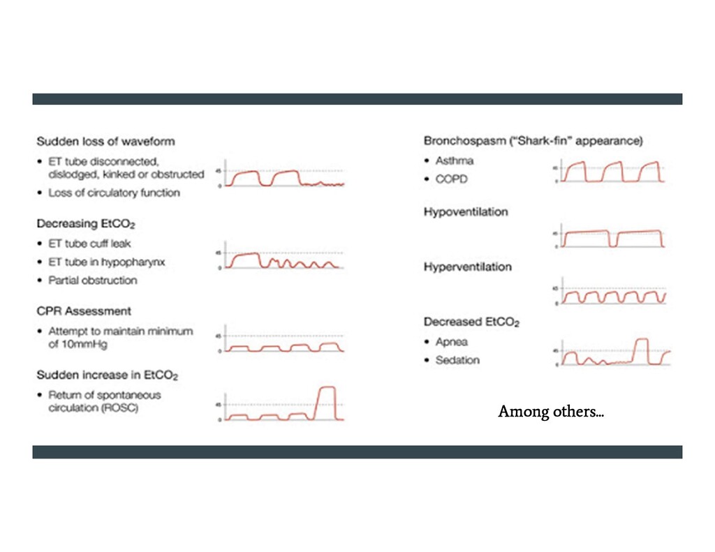
the most important monitor we have. Facilitates confirmation of ETT position, as well as an indirect understanding of a patient’s: metabolism, minute ventilation, acid-base status, cardiopulmonary circulation, dead space ventilation, exhalation pattern, degree of bronchospasm or obstructive lung disease, adequacy of CPR, adequacy of CO2 scrubbing chemicals in circle breathing system canister, and others
Nihon Kohden using the ratio of red to infrared light absorption of pulsating components at the measuring site. Susumu Nakajima, a surgeon, and his associates first tested the device in patients, reporting it in 1975. Commercialized in 1980. By 1987, became the standard of care during administration of general anesthesia in the U.S.
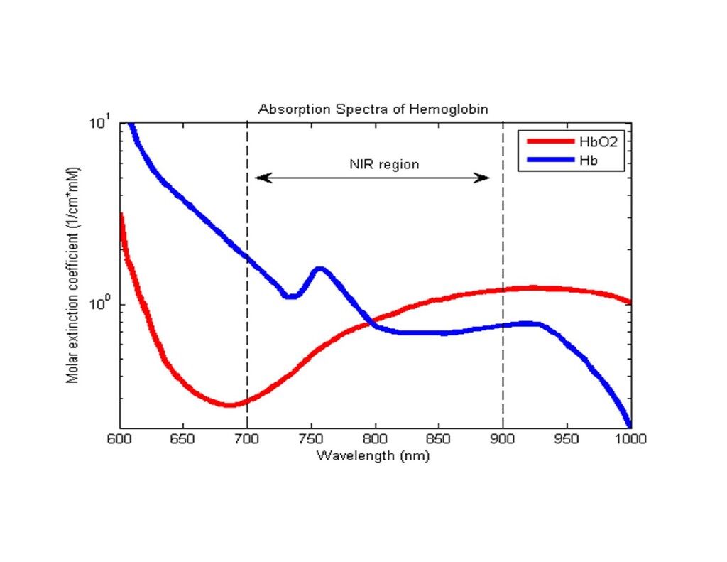
the other infrared at 940 nm. -Absorption of light at these two wavelengths differs significantly between blood loaded with oxygen and blood lacking oxygen. - Oxygenated hemoglobin absorbs more infrared light and less red than de-oxygenated. - The LEDs sequence through their cycle of one on, then the other, then both off about thirty times per second. This is then averaged.
will occur when Hb binds to something other than oxygen. - Hemoglobin has a higher affinity to CO than O2. High reading may occur despite the patient actually being hypoxemic. - Cyanide poisoning gives a high reading because it reduces oxygen extraction from arterial blood. In this case, the reading is not false. - Methemoglobinemia characteristically causes pulse oximetry readings in the mid-80s.
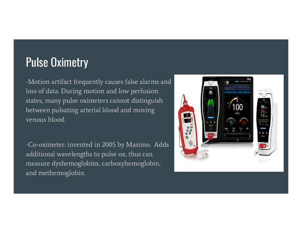
of data. During motion and low perfusion states, many pulse oximeters cannot distinguish between pulsating arterial blood and moving venous blood. -Co-oximeter: invented in 2005 by Masimo. Adds additional wavelengths to pulse ox, thus can measure dyshemoglobins, carboxyhemoglobin, and methemoglobin.
from https://www.openanesthesia.org/airway_fire_mgmt/ Barash, P. G. (2017). Clinical anesthesia. Philadelphia: Wolters Kluwer. Capnography as a Clinical Tool. By, S., & Wampler, D. (2011, June 28). Retrieved October 25, 2020, from https://www.emsworld.com/article/10287447/capnography- clinical-tool Fire Safety in the Operating Room Video. (2020, February 29). Retrieved October 25, 2020, from https://www.apsf.org/videos/or-fire-safety-video/