11th Production art director In the Ace Combat series, mainly in charge of environment, mechanical design, lighting, etc. Shohei Yamaguchi BANDAI NAMCO Studios Inc. Technology Studio Core Technology Department Support Section TA Part Engineer Formerly TD of CG for live-action video, Now in charge of color management, lighting, etc. Masayuki Suzuki BANDAI NAMCO Studios Inc. Technology Studio Core Technology Department Support Section TA Part As a TA, in charge of graphic research, project support, and lighting.
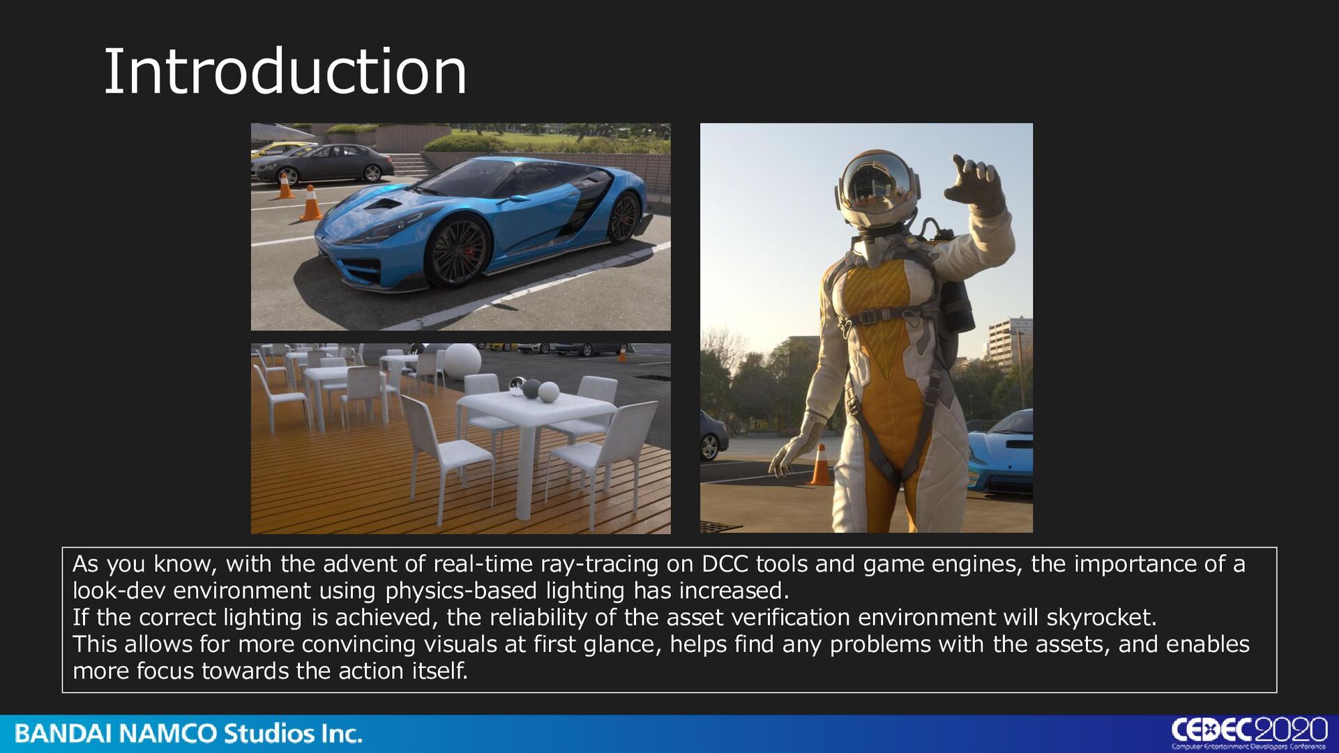
on DCC tools and game engines, the importance of a look-dev environment using physics-based lighting has increased. If the correct lighting is achieved, the reliability of the asset verification environment will skyrocket. This allows for more convincing visuals at first glance, helps find any problems with the assets, and enables more focus towards the action itself.
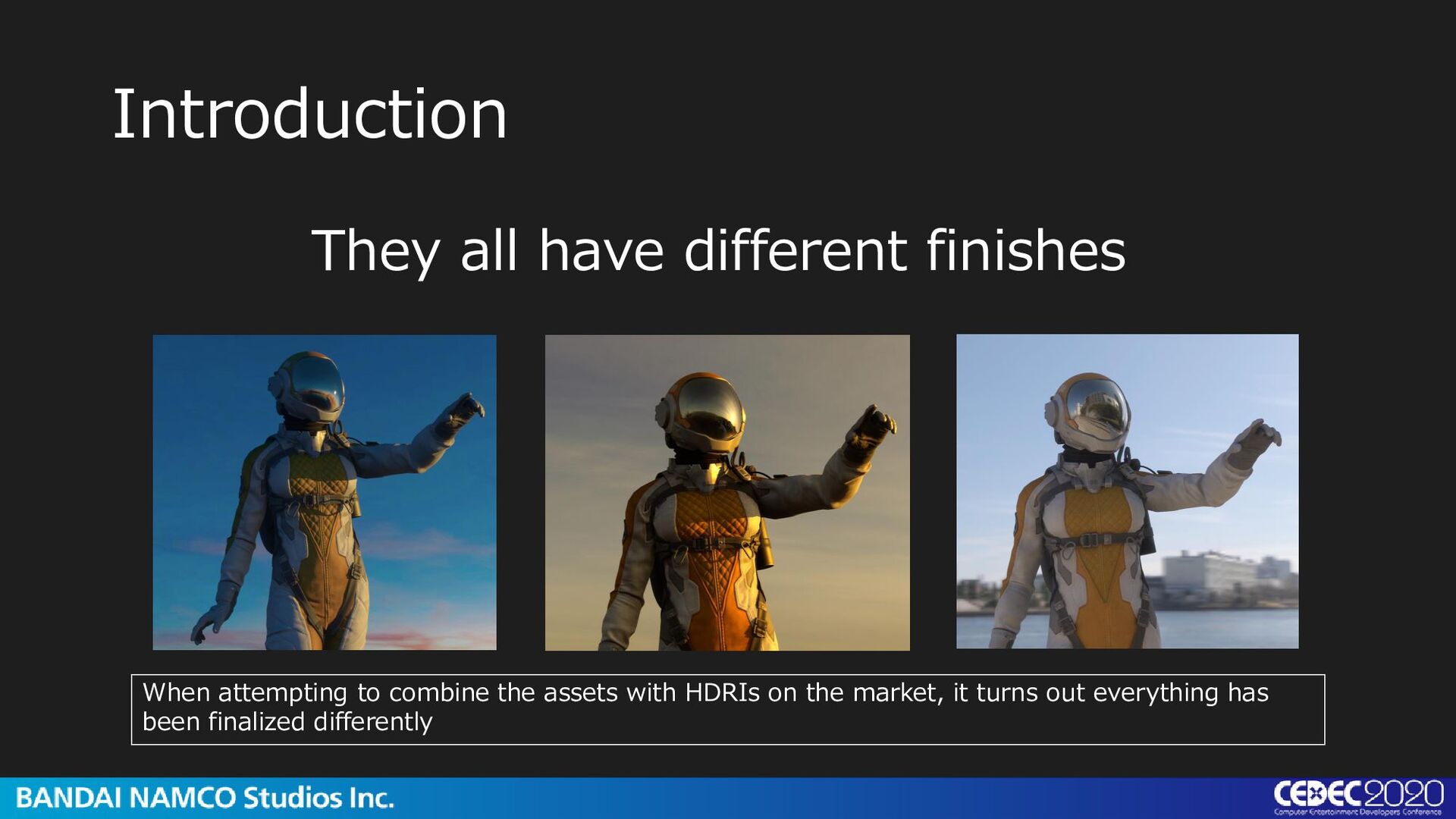
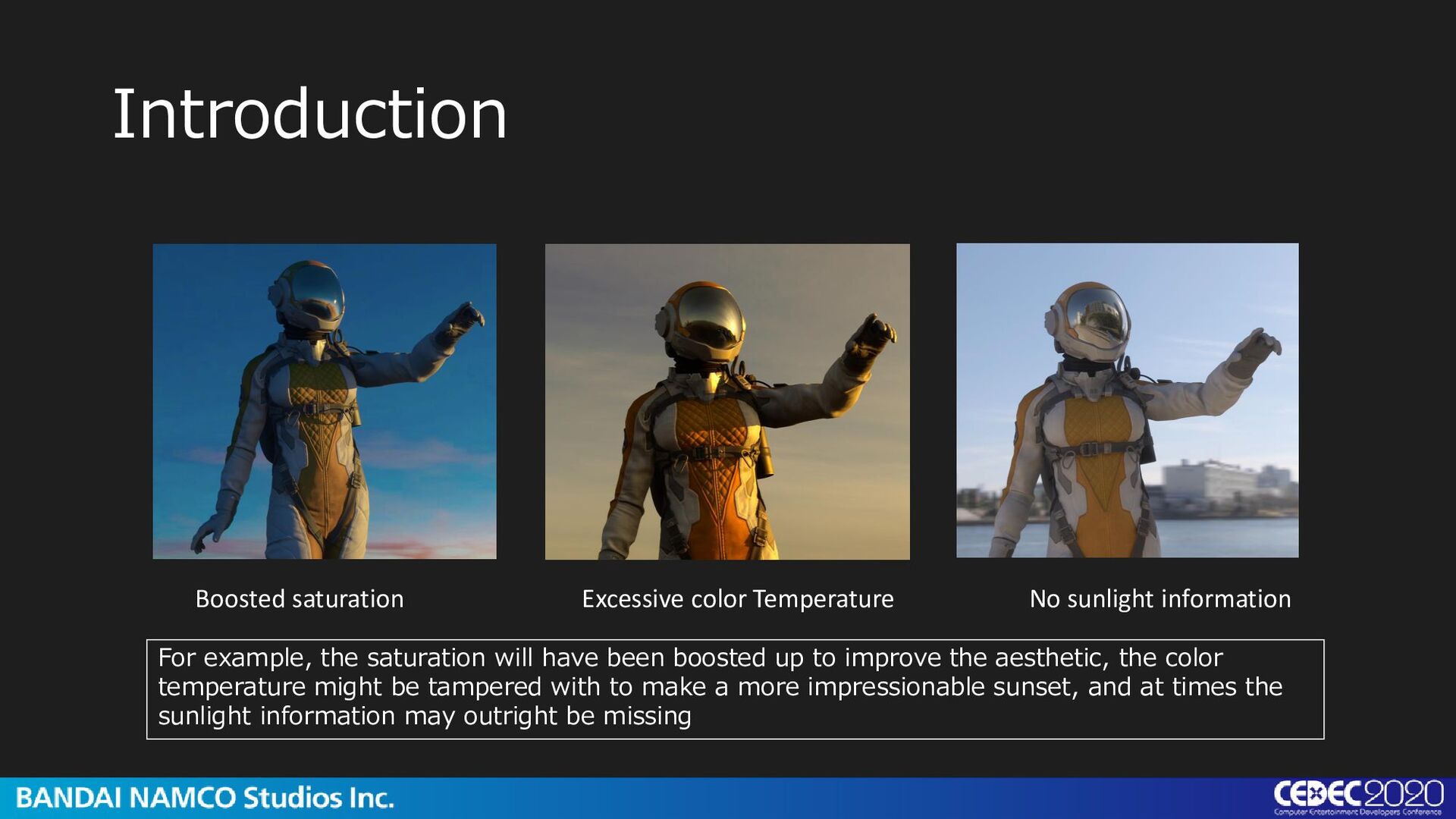
example, the saturation will have been boosted up to improve the aesthetic, the color temperature might be tampered with to make a more impressionable sunset, and at times the sunlight information may outright be missing
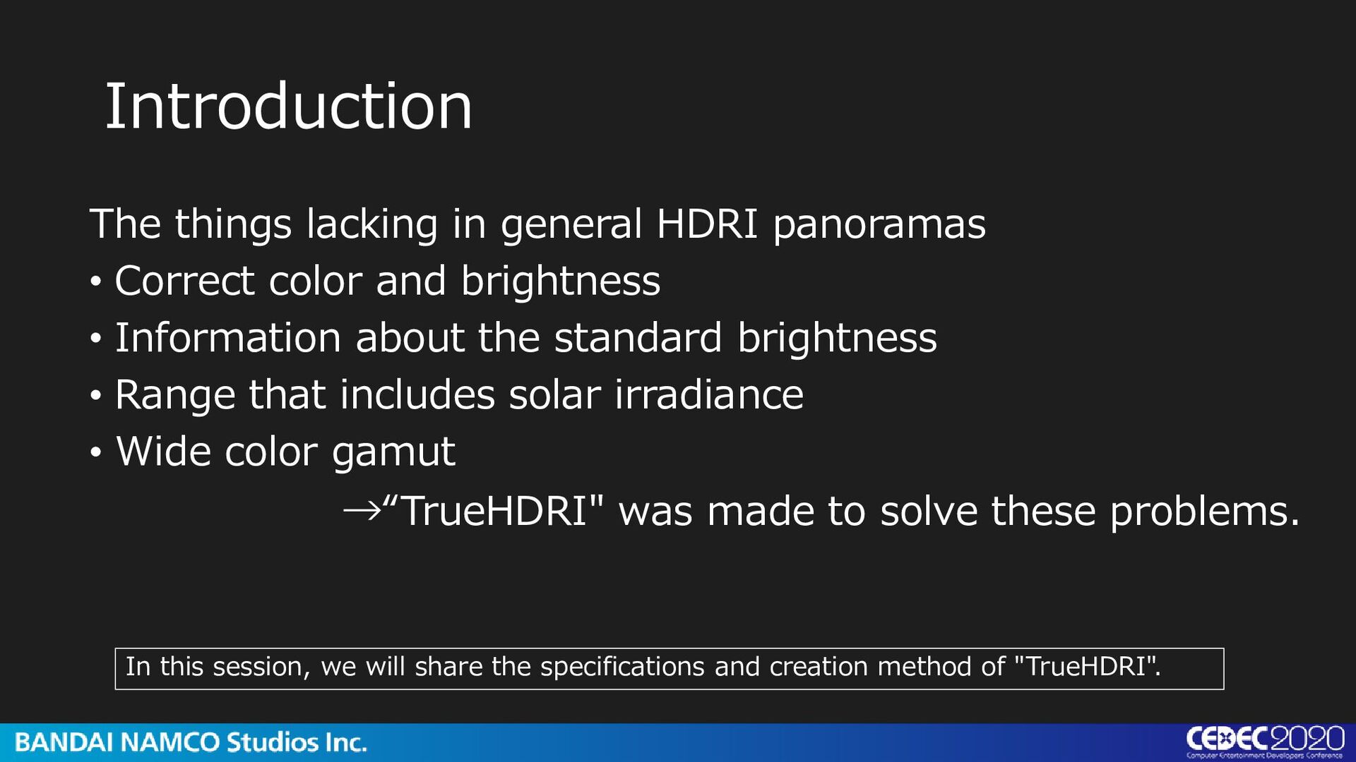
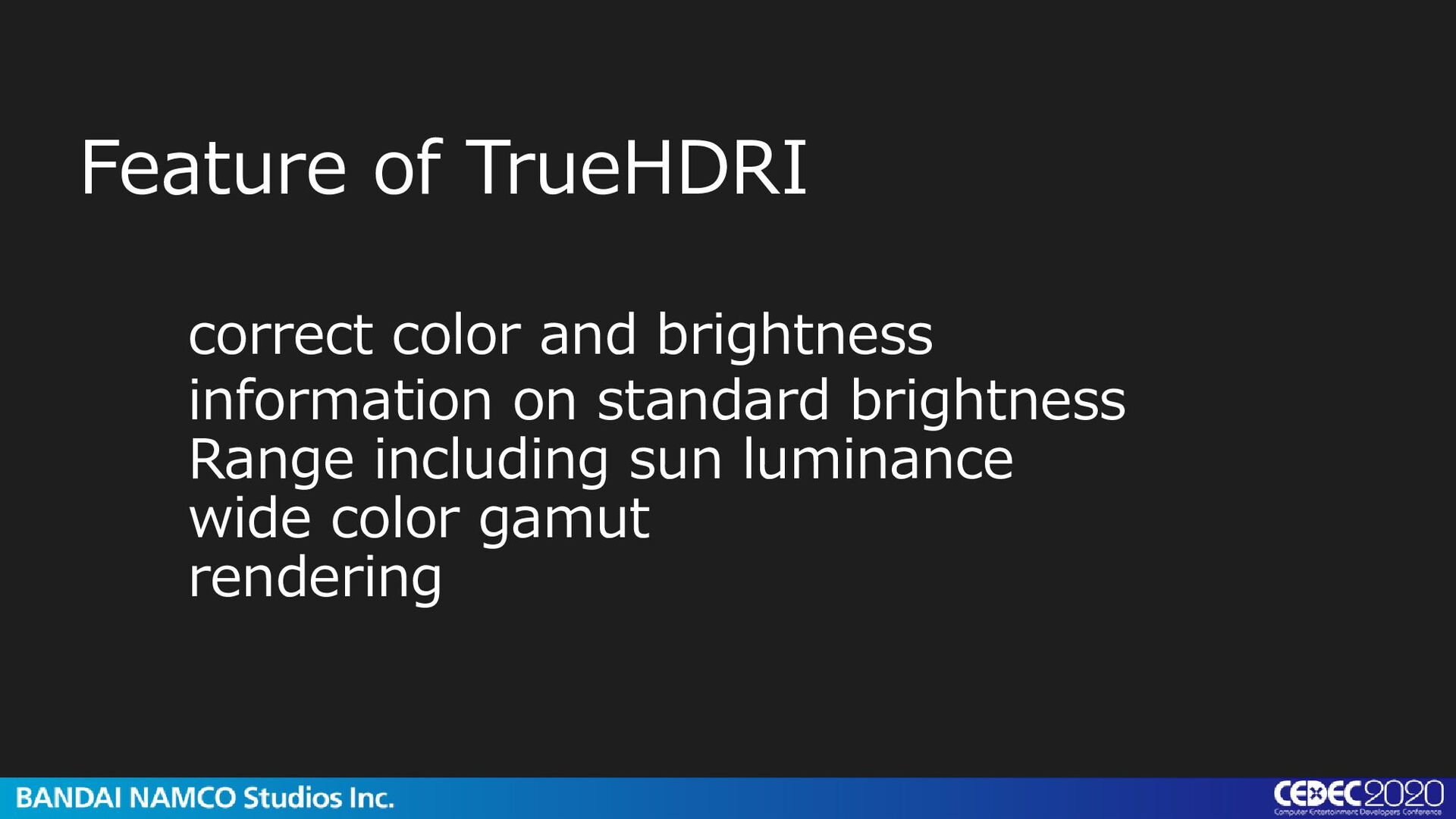
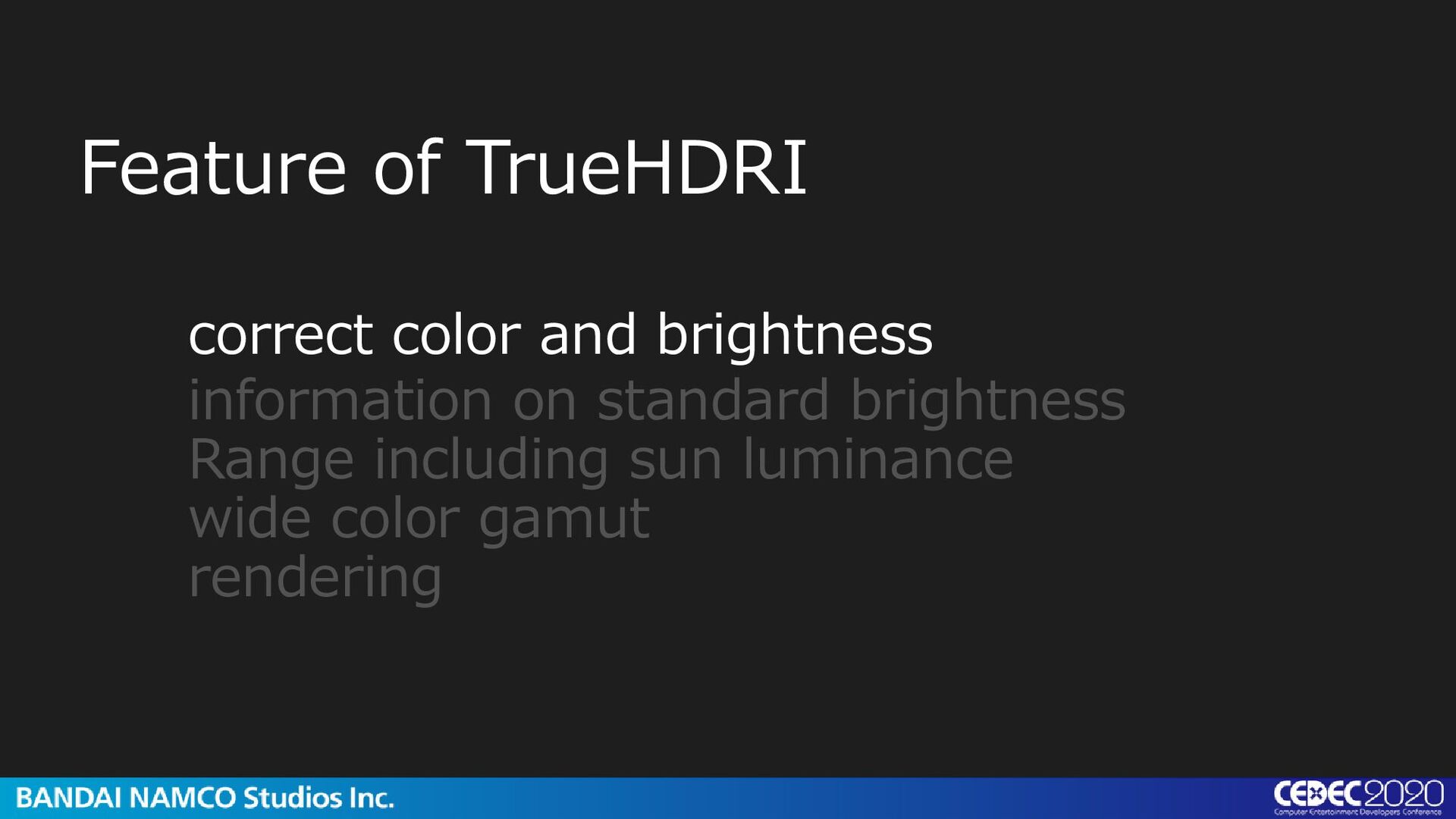
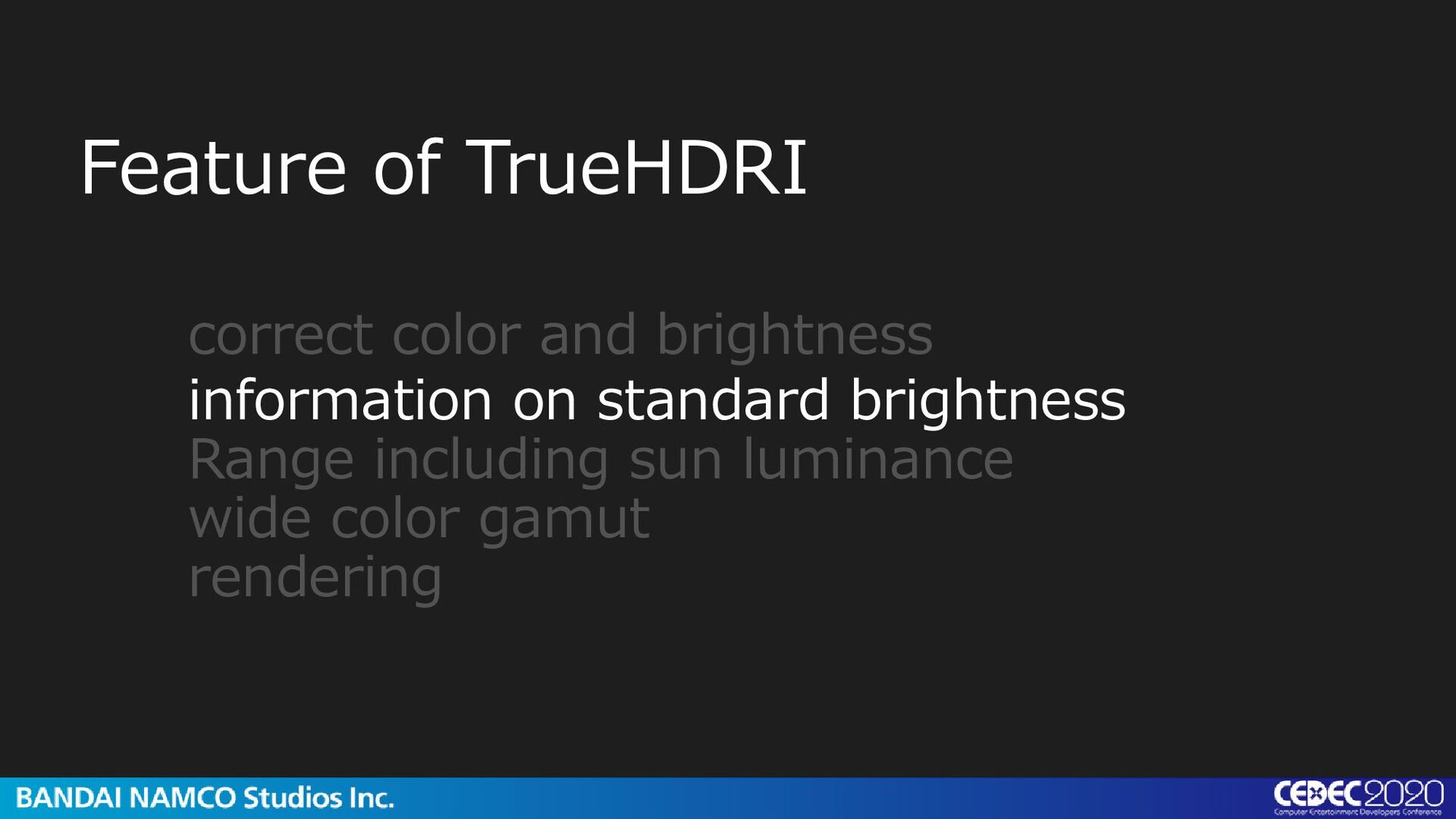
color and brightness • Information about the standard brightness • Range that includes solar irradiance • Wide color gamut →“TrueHDRI" was made to solve these problems. In this session, we will share the specifications and creation method of "TrueHDRI".
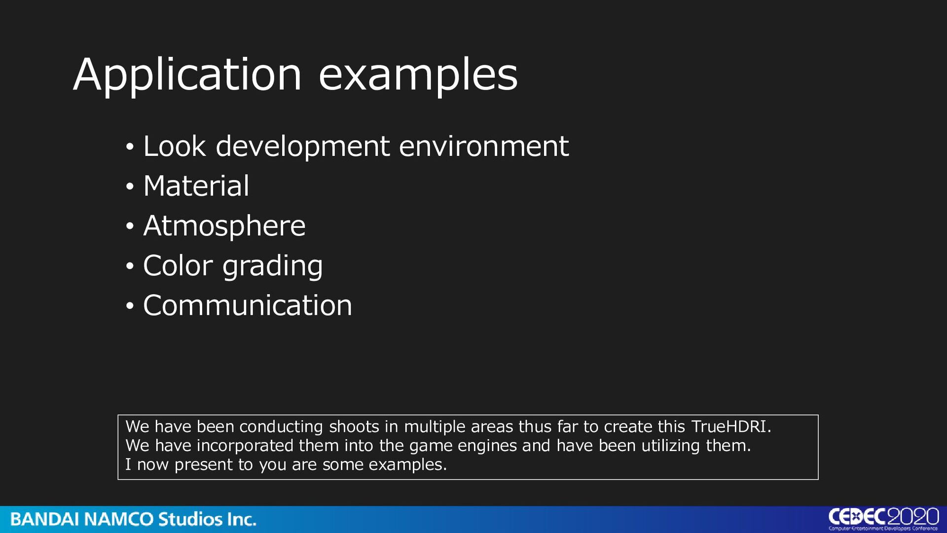
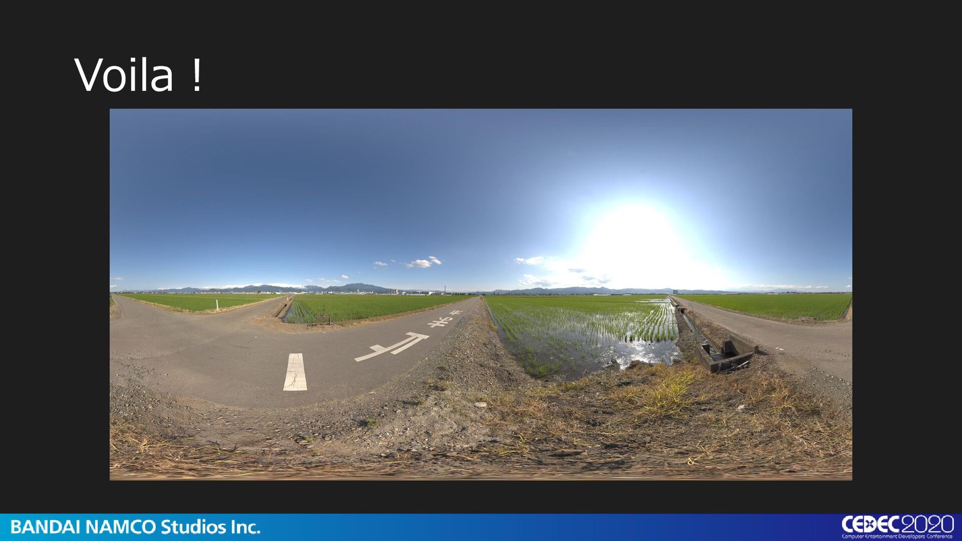
• Color grading • Communication We have been conducting shoots in multiple areas thus far to create this TrueHDRI. We have incorporated them into the game engines and have been utilizing them. I now present to you are some examples.
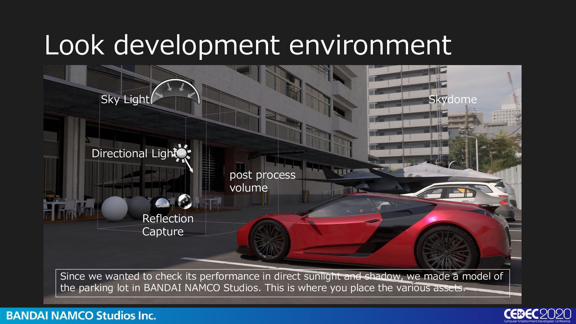
process volume Skydome Since we wanted to check its performance in direct sunlight and shadow, we made a model of the parking lot in BANDAI NAMCO Studios. This is where you place the various assets.
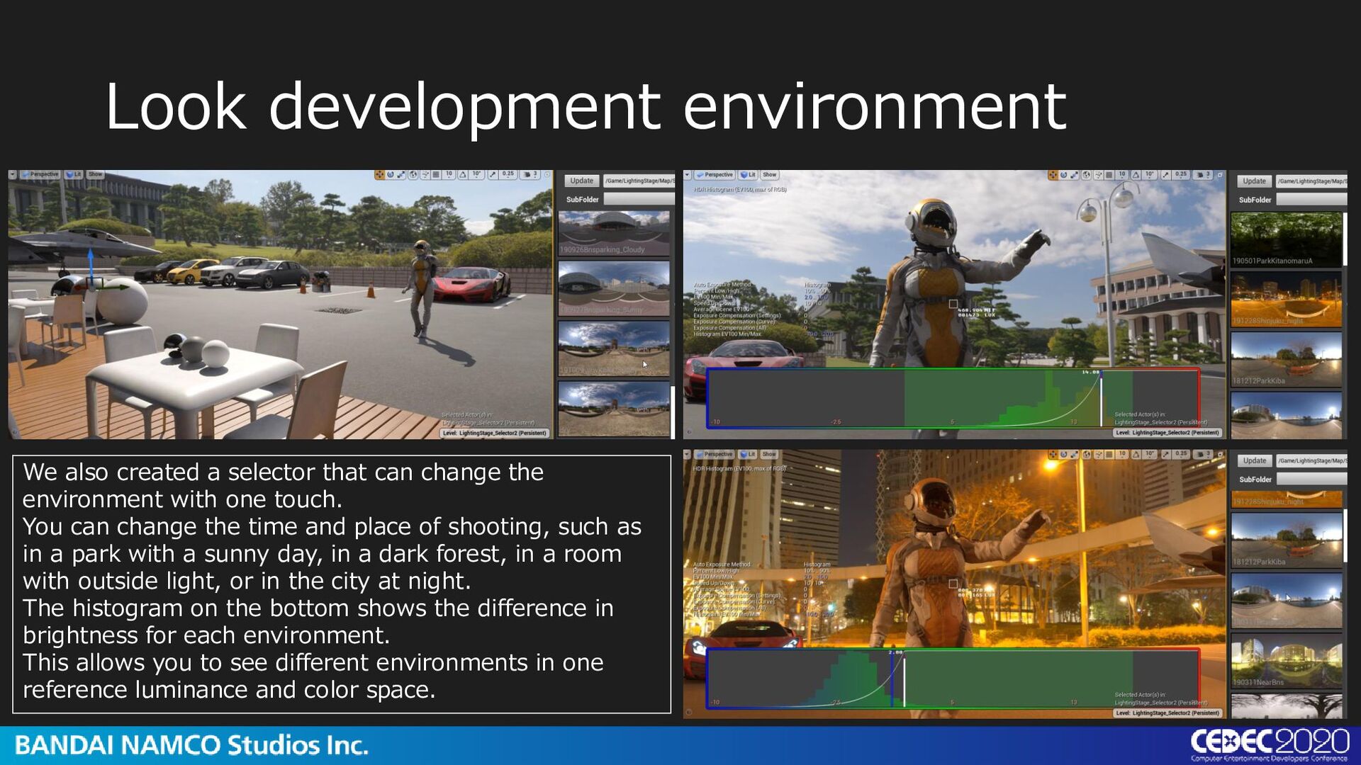
change the environment with one touch. You can change the time and place of shooting, such as in a park with a sunny day, in a dark forest, in a room with outside light, or in the city at night. The histogram on the bottom shows the difference in brightness for each environment. This allows you to see different environments in one reference luminance and color space.
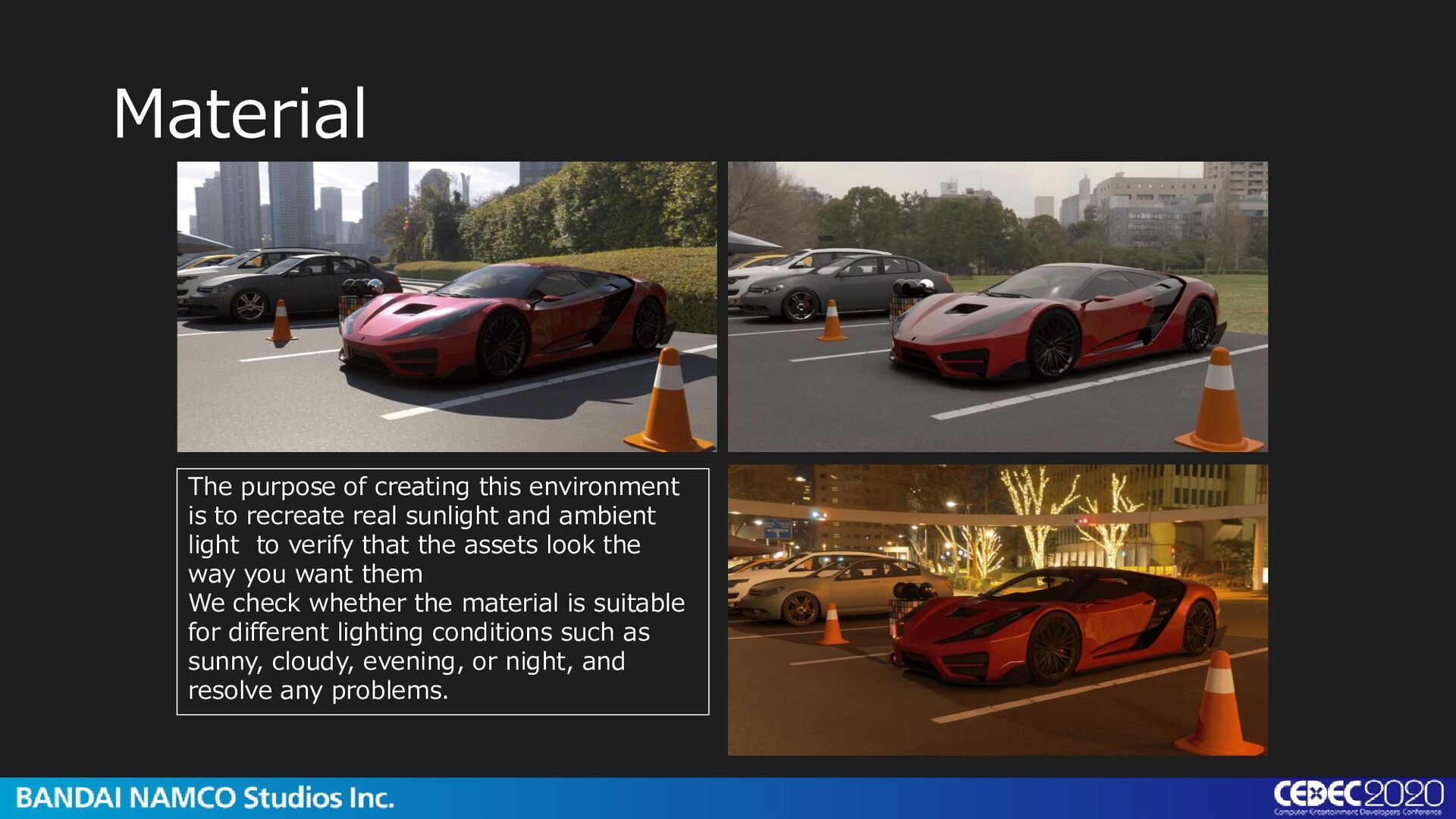
real sunlight and ambient light to verify that the assets look the way you want them We check whether the material is suitable for different lighting conditions such as sunny, cloudy, evening, or night, and resolve any problems.
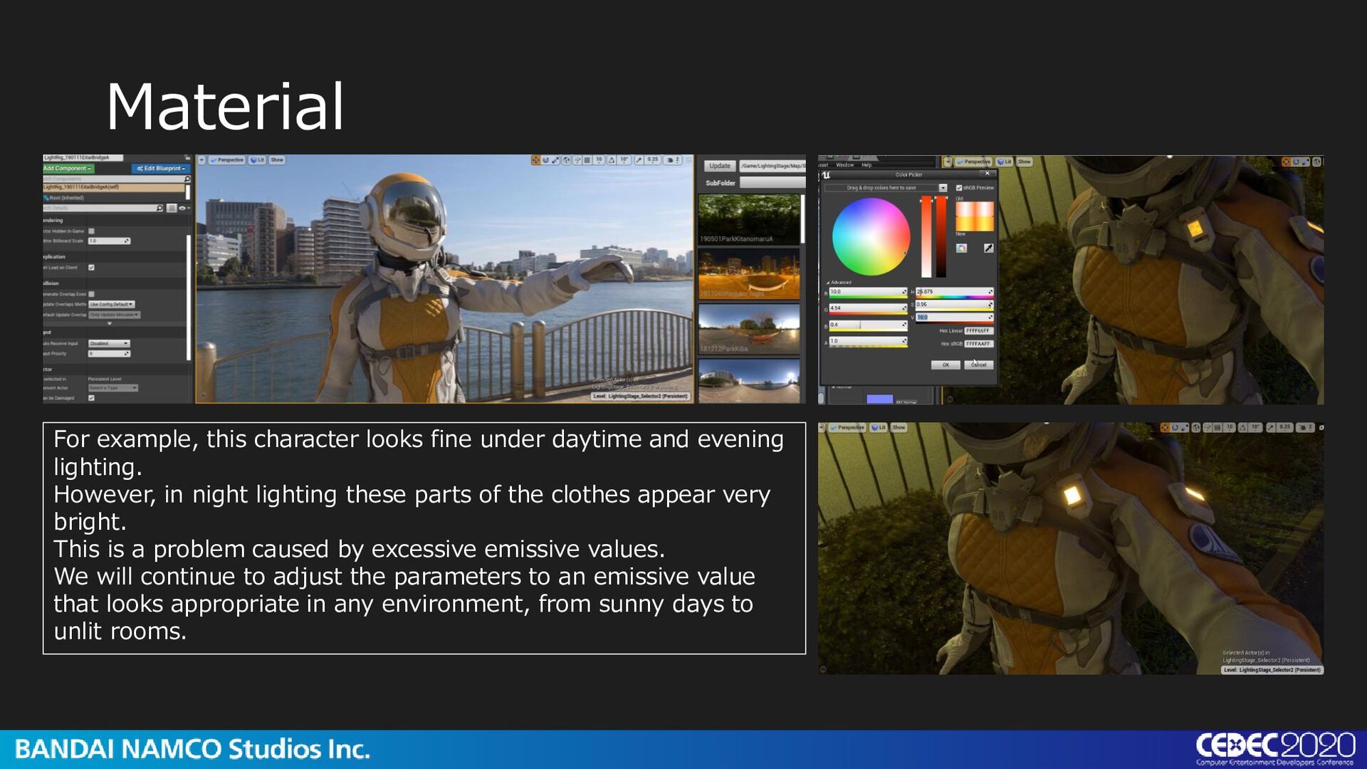
evening lighting. However, in night lighting these parts of the clothes appear very bright. This is a problem caused by excessive emissive values. We will continue to adjust the parameters to an emissive value that looks appropriate in any environment, from sunny days to unlit rooms.
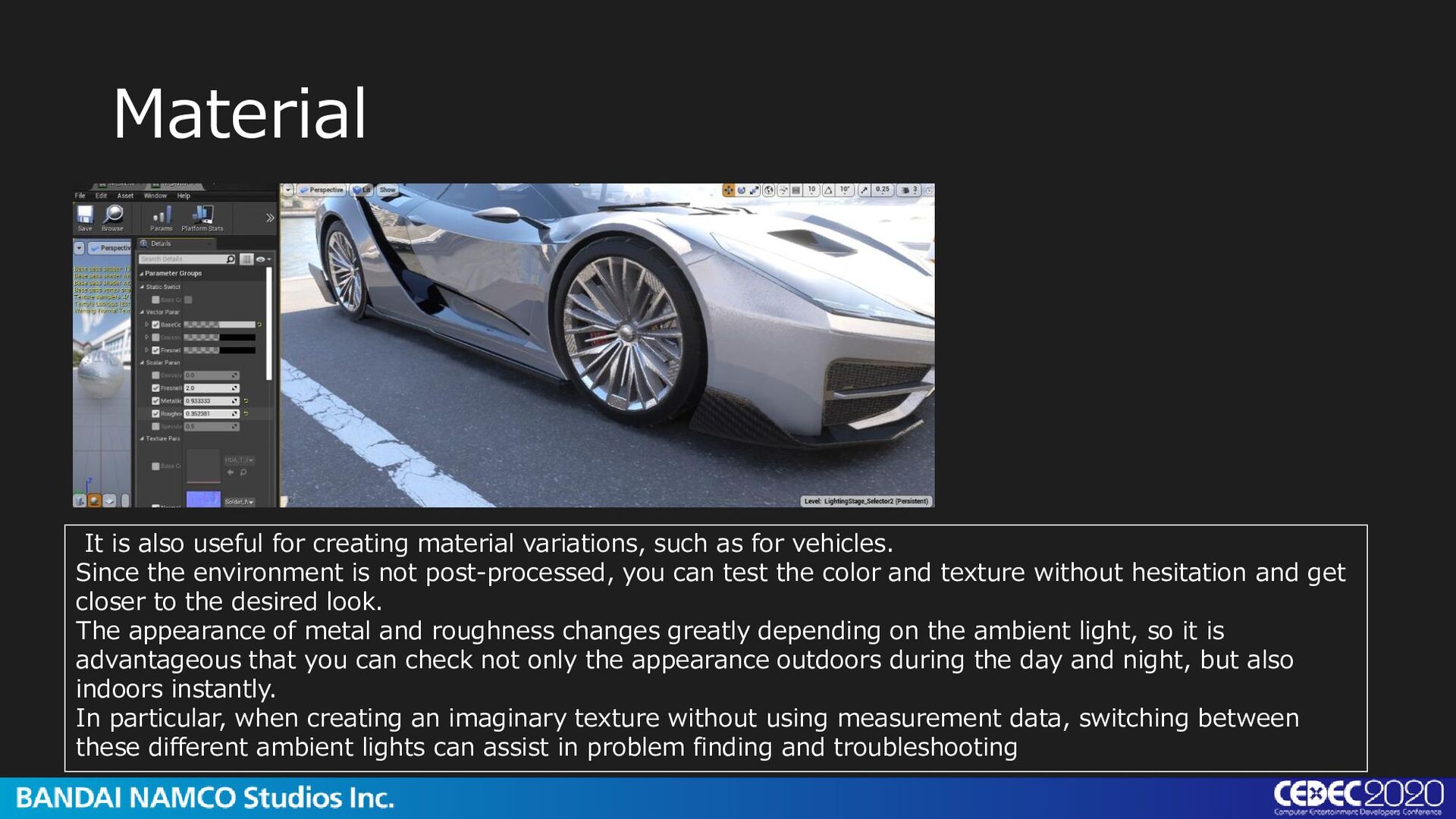
as for vehicles. Since the environment is not post-processed, you can test the color and texture without hesitation and get closer to the desired look. The appearance of metal and roughness changes greatly depending on the ambient light, so it is advantageous that you can check not only the appearance outdoors during the day and night, but also indoors instantly. In particular, when creating an imaginary texture without using measurement data, switching between these different ambient lights can assist in problem finding and troubleshooting
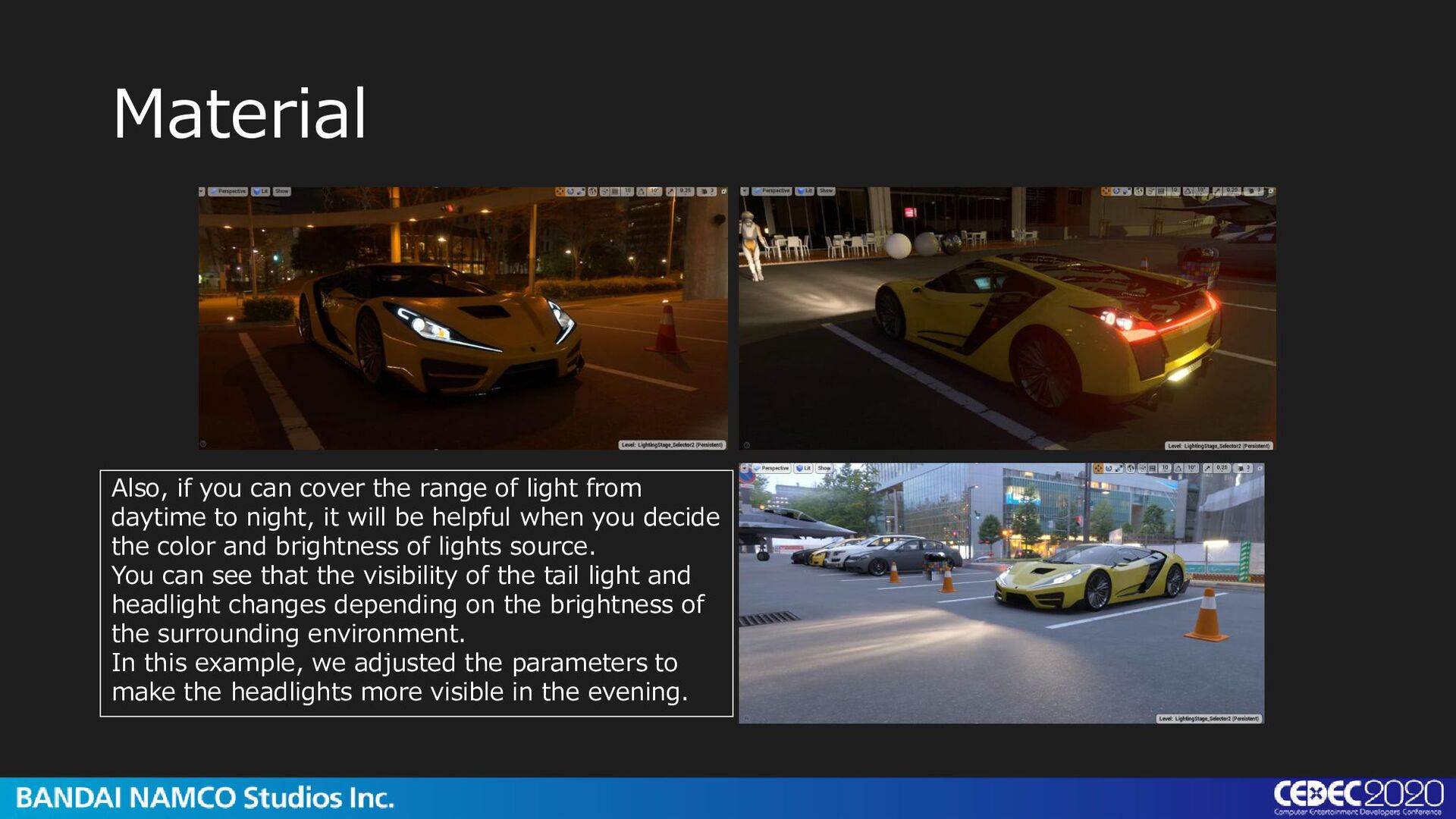
from daytime to night, it will be helpful when you decide the color and brightness of lights source. You can see that the visibility of the tail light and headlight changes depending on the brightness of the surrounding environment. In this example, we adjusted the parameters to make the headlights more visible in the evening.
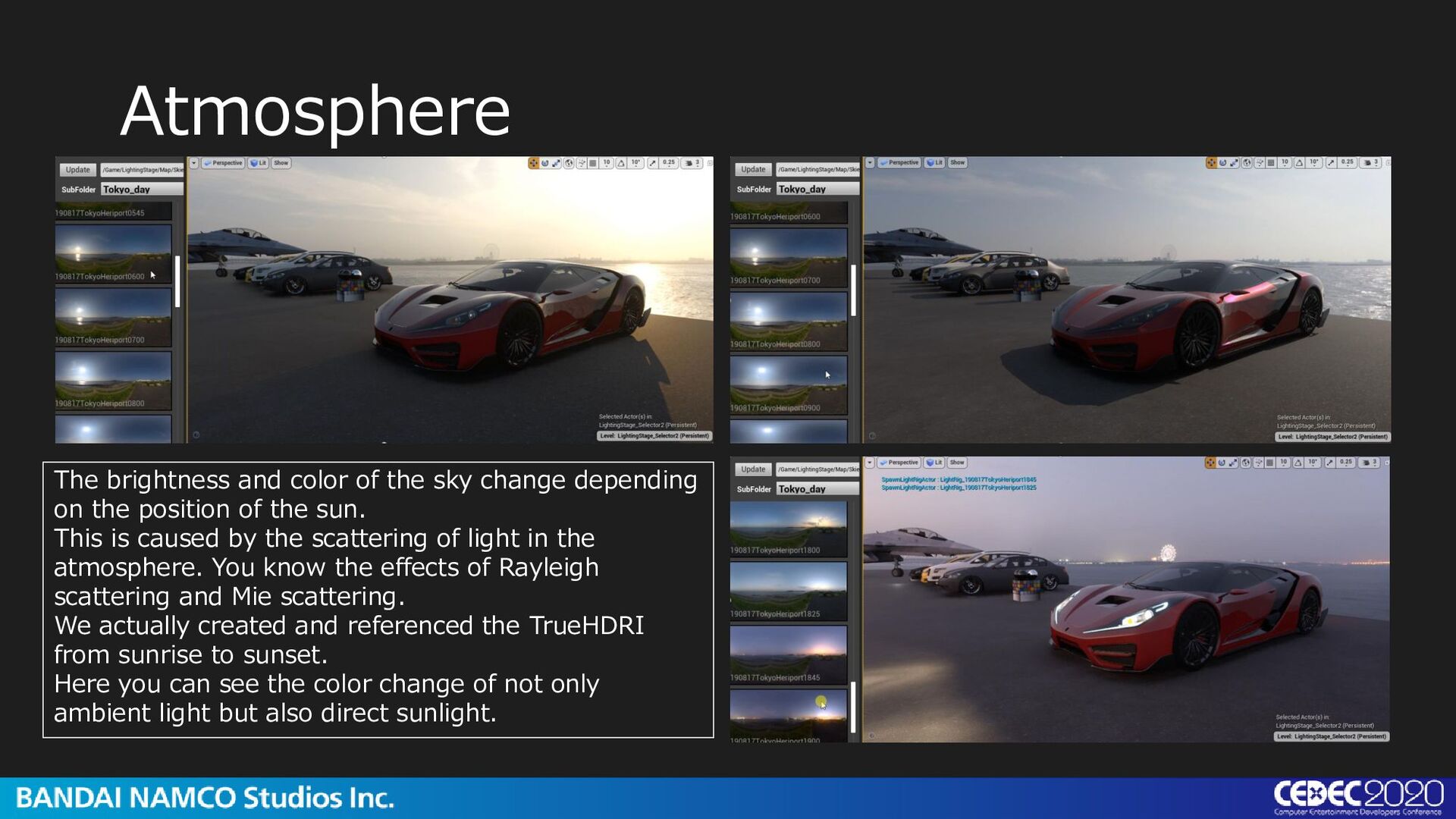
on the position of the sun. This is caused by the scattering of light in the atmosphere. You know the effects of Rayleigh scattering and Mie scattering. We actually created and referenced the TrueHDRI from sunrise to sunset. Here you can see the color change of not only ambient light but also direct sunlight.
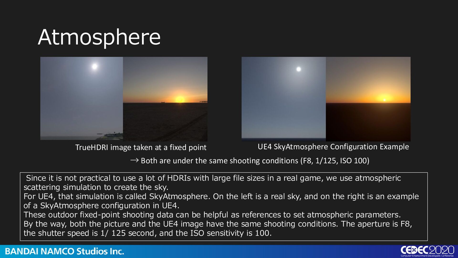
Configuration Example → Both are under the same shooting conditions (F8, 1/125, ISO 100) Since it is not practical to use a lot of HDRIs with large file sizes in a real game, we use atmospheric scattering simulation to create the sky. For UE4, that simulation is called SkyAtmosphere. On the left is a real sky, and on the right is an example of a SkyAtmosphere configuration in UE4. These outdoor fixed-point shooting data can be helpful as references to set atmospheric parameters. By the way, both the picture and the UE4 image have the same shooting conditions. The aperture is F8, the shutter speed is 1/ 125 second, and the ISO sensitivity is 100.
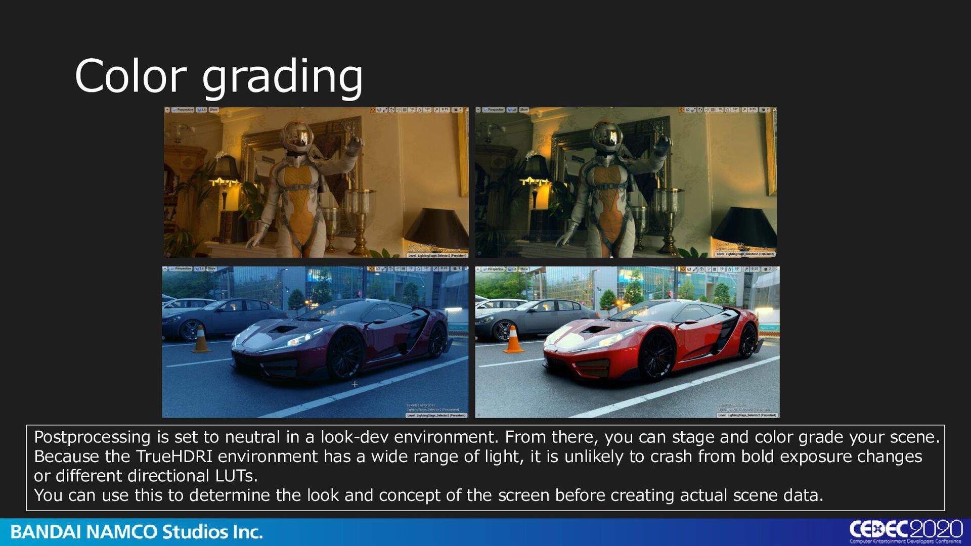
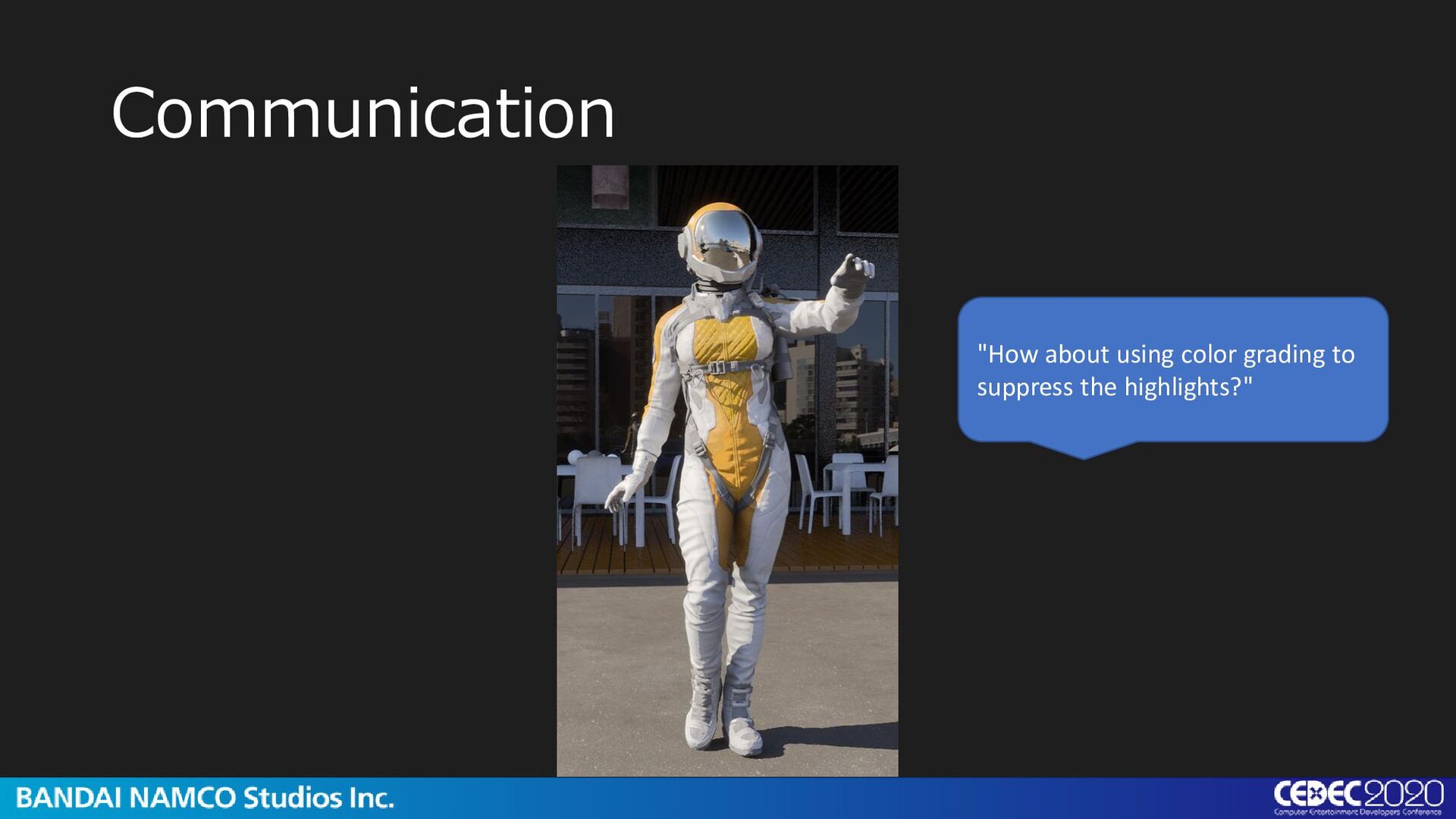
environment. From there, you can stage and color grade your scene. Because the TrueHDRI environment has a wide range of light, it is unlikely to crash from bold exposure changes or different directional LUTs. You can use this to determine the look and concept of the screen before creating actual scene data.
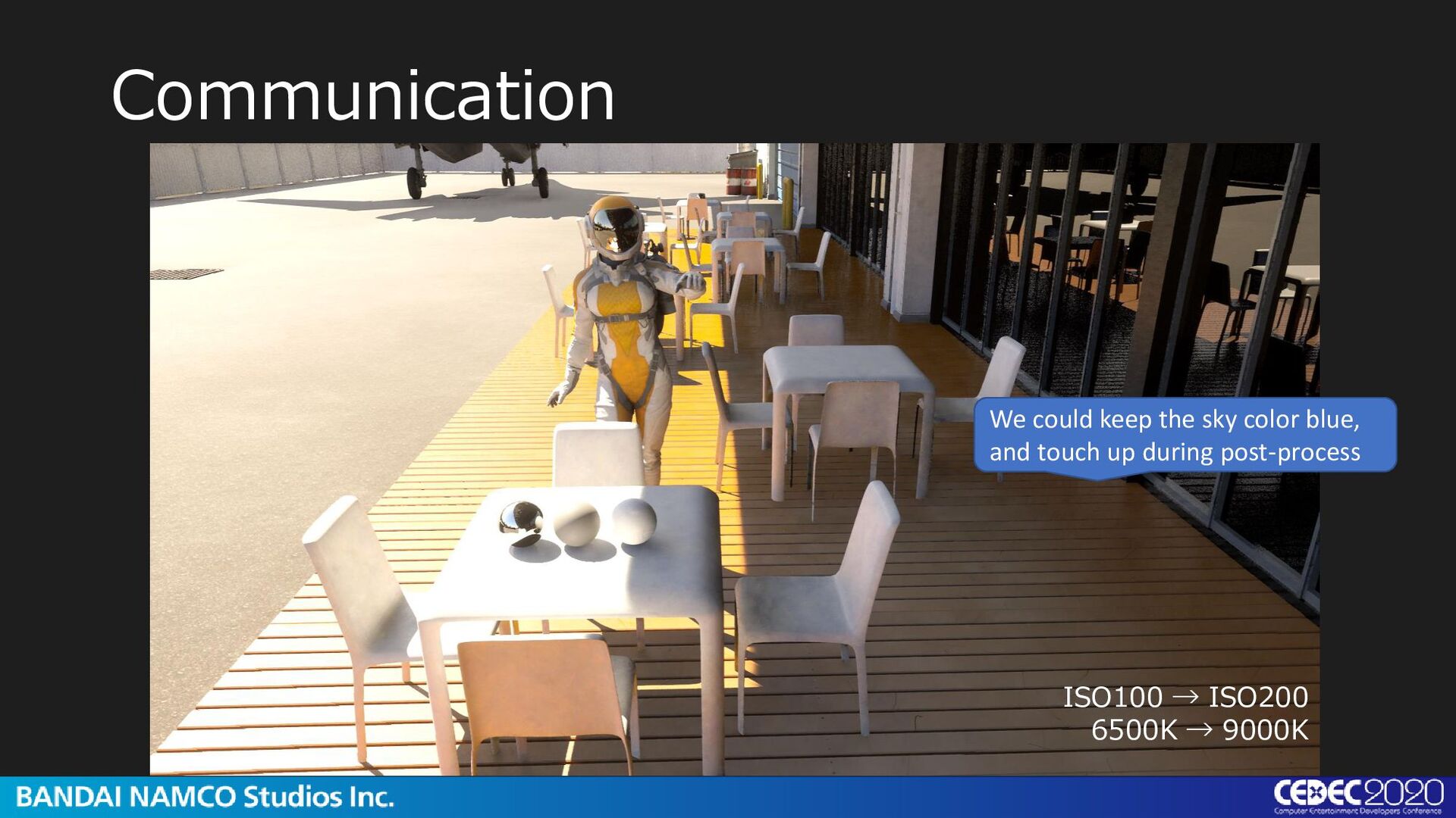
is clearly established in TrueHDRI, it can support UE4 camera simulations This means that the shutter speed, aperture and ISO sensitivity information of a real camera can be applied. It can also be a useful environment for people familiar with cameras.
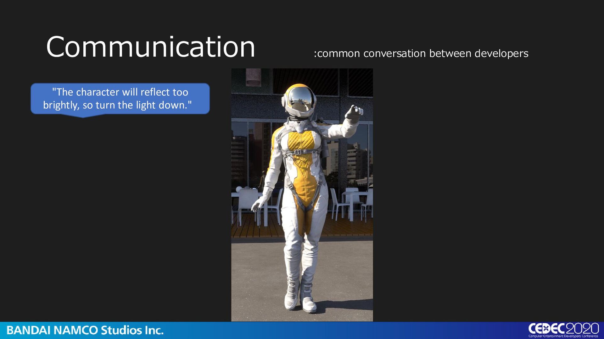
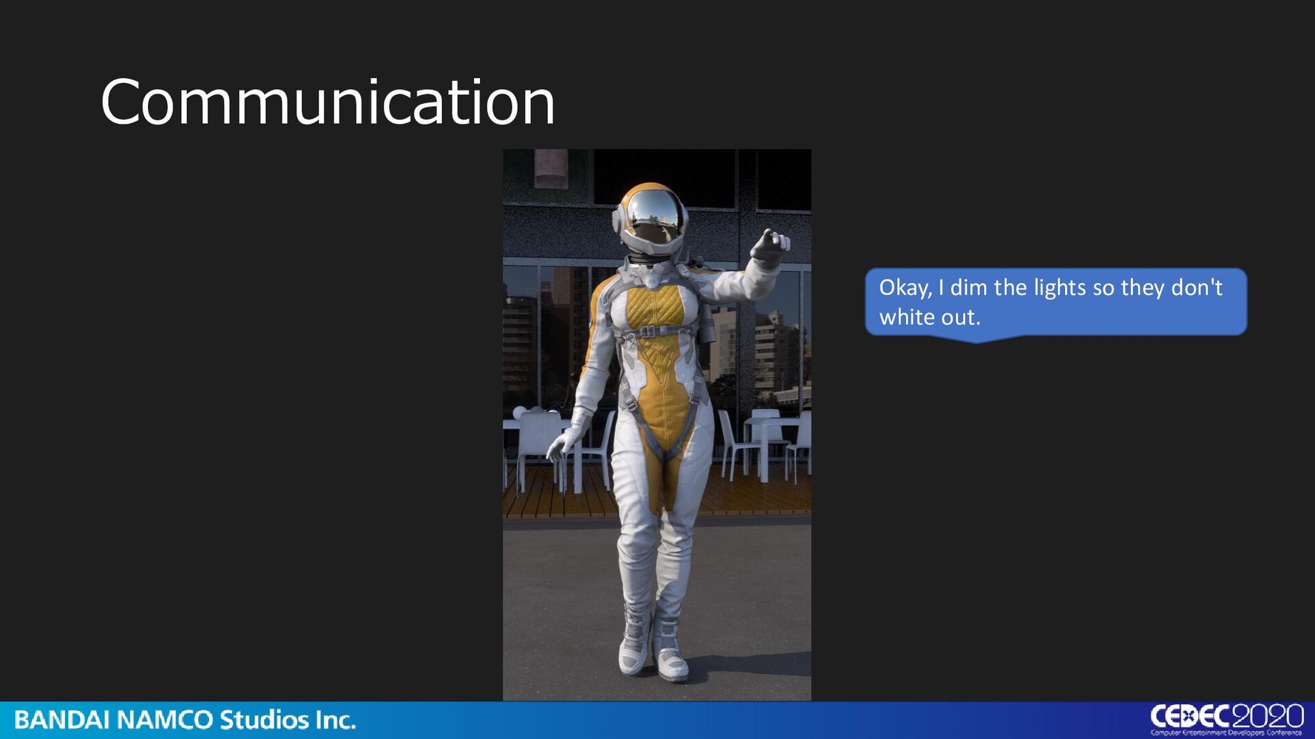
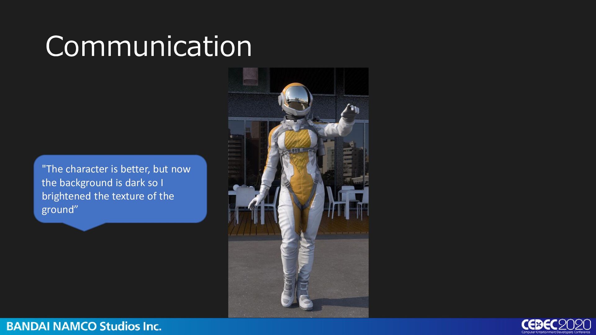
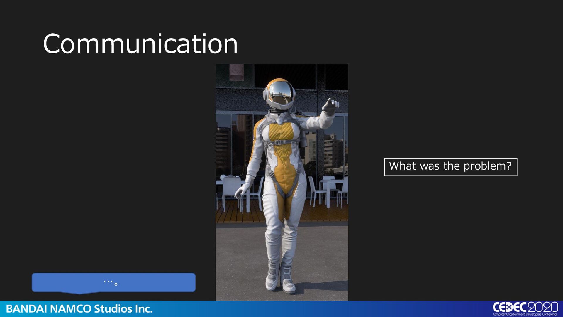
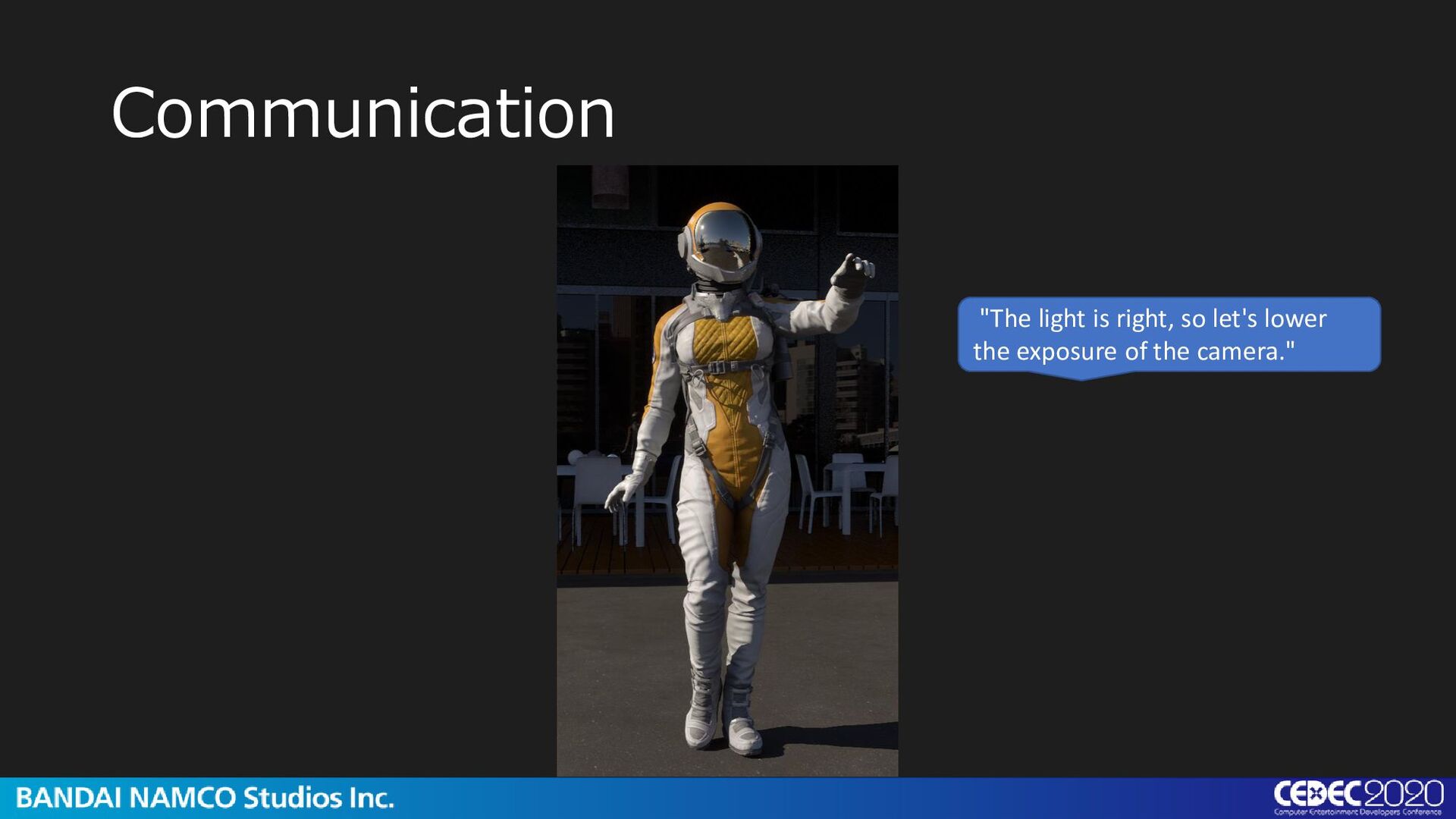
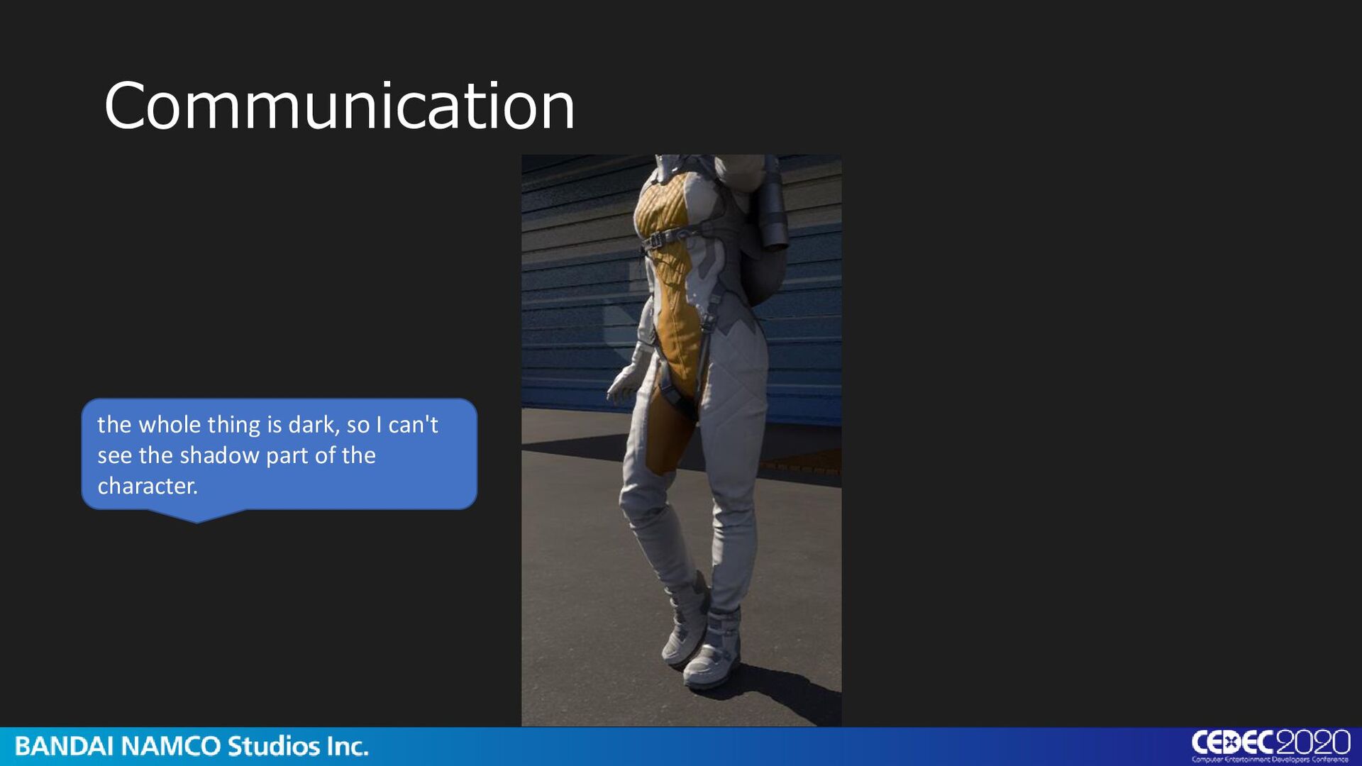
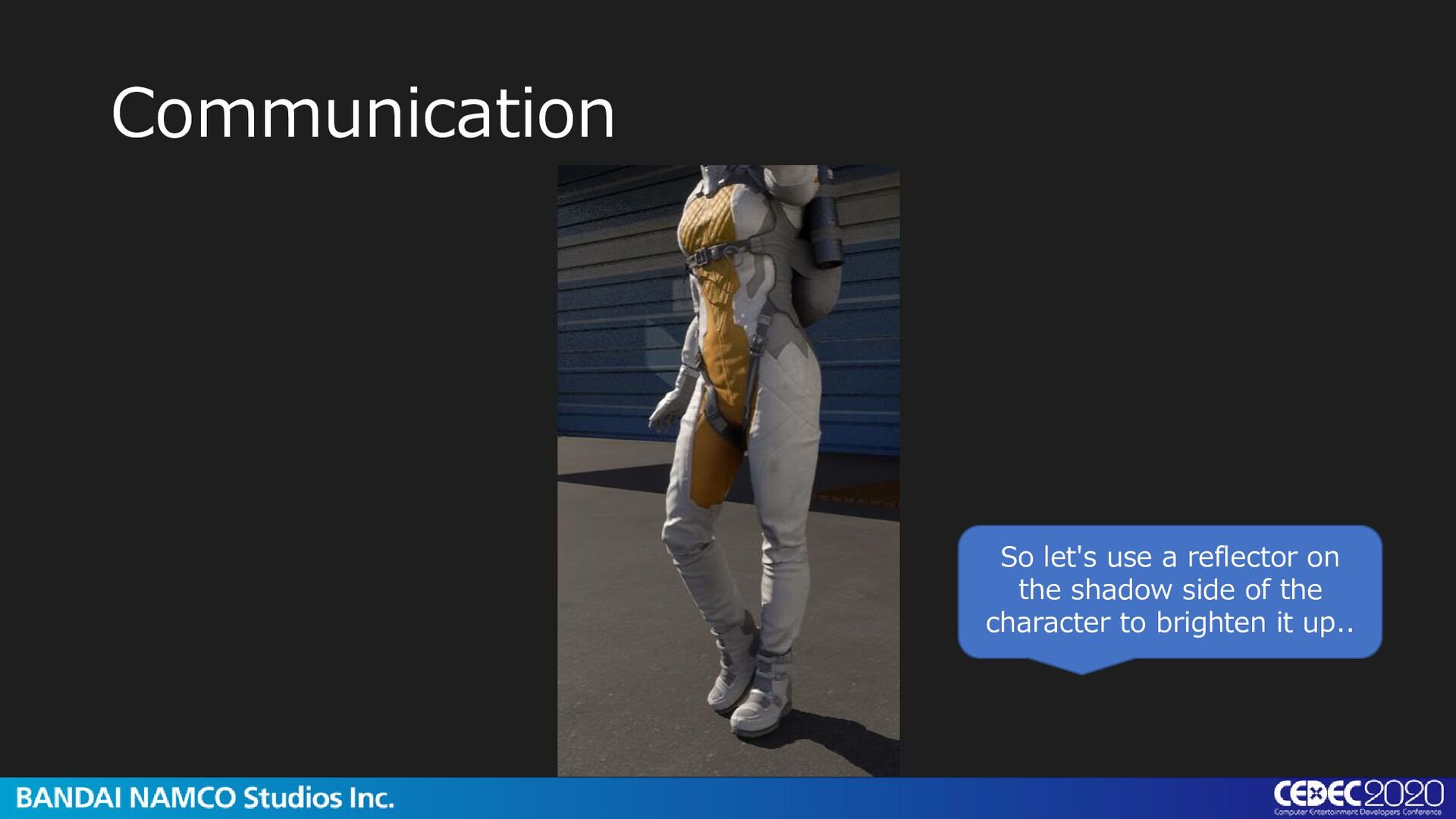
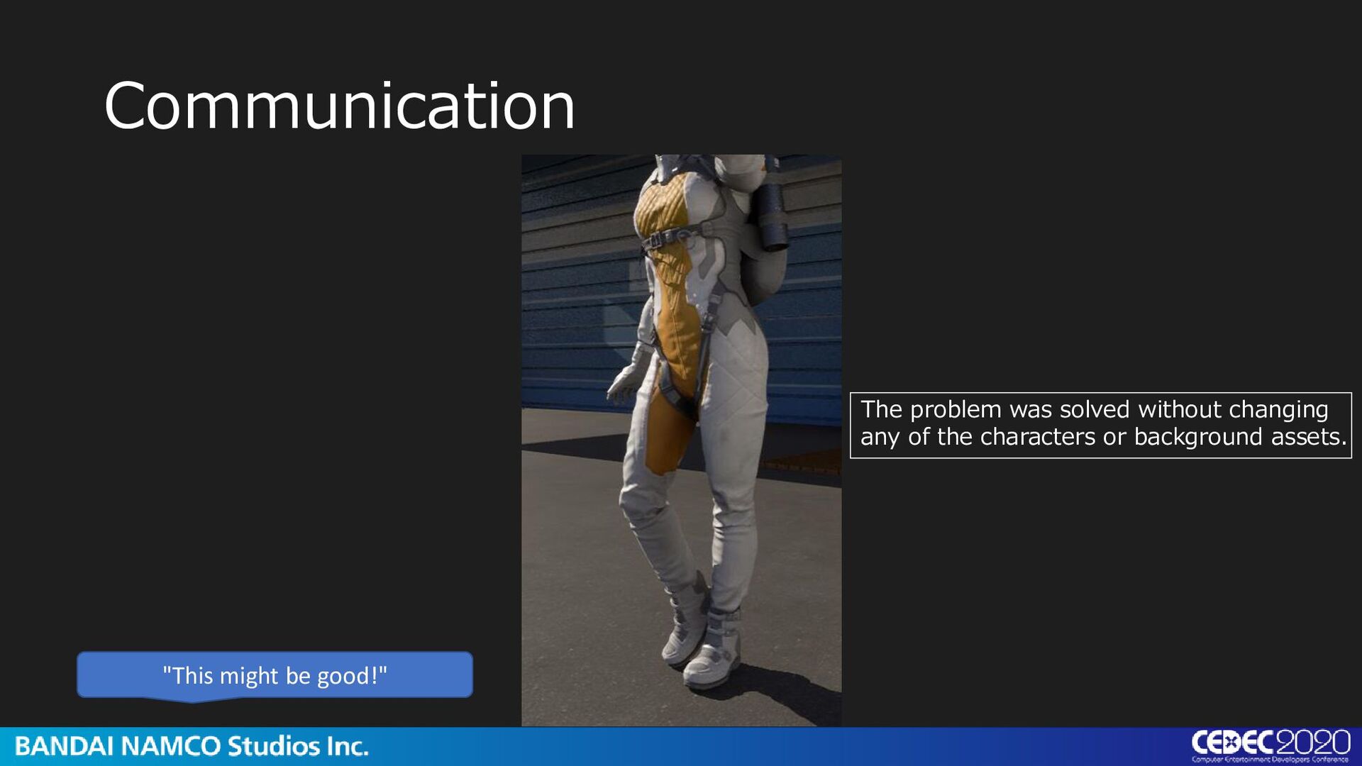
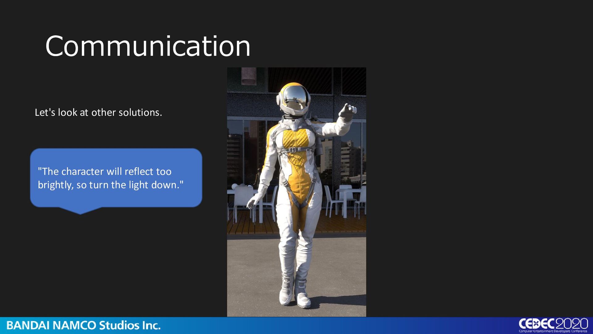
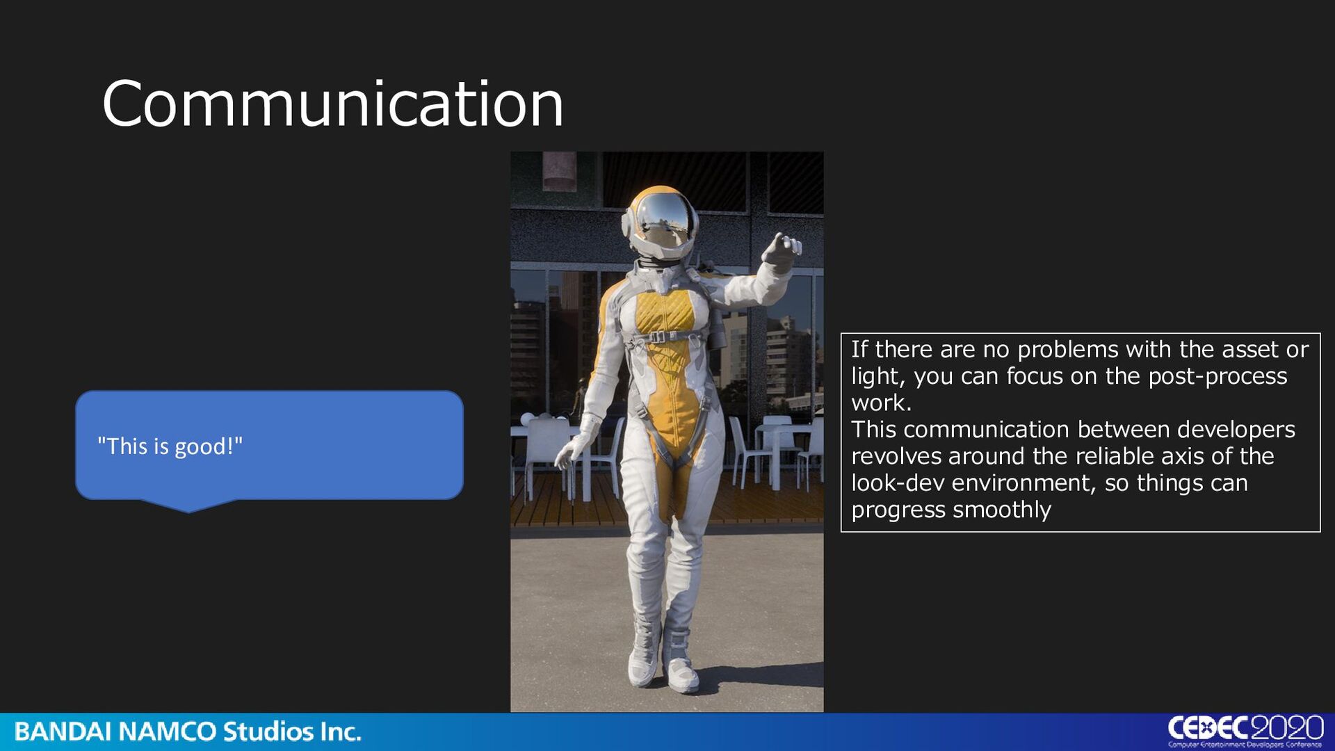
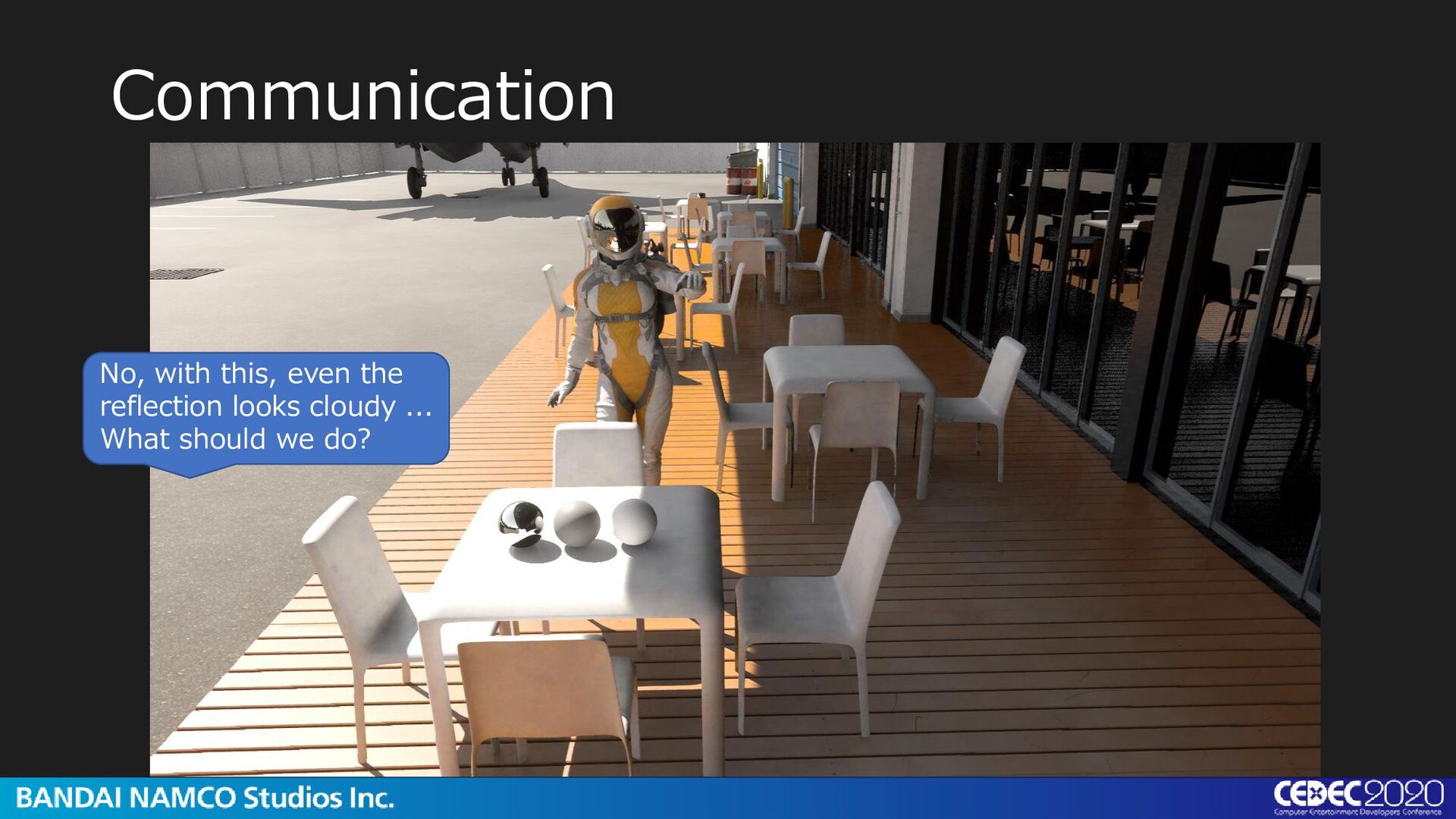
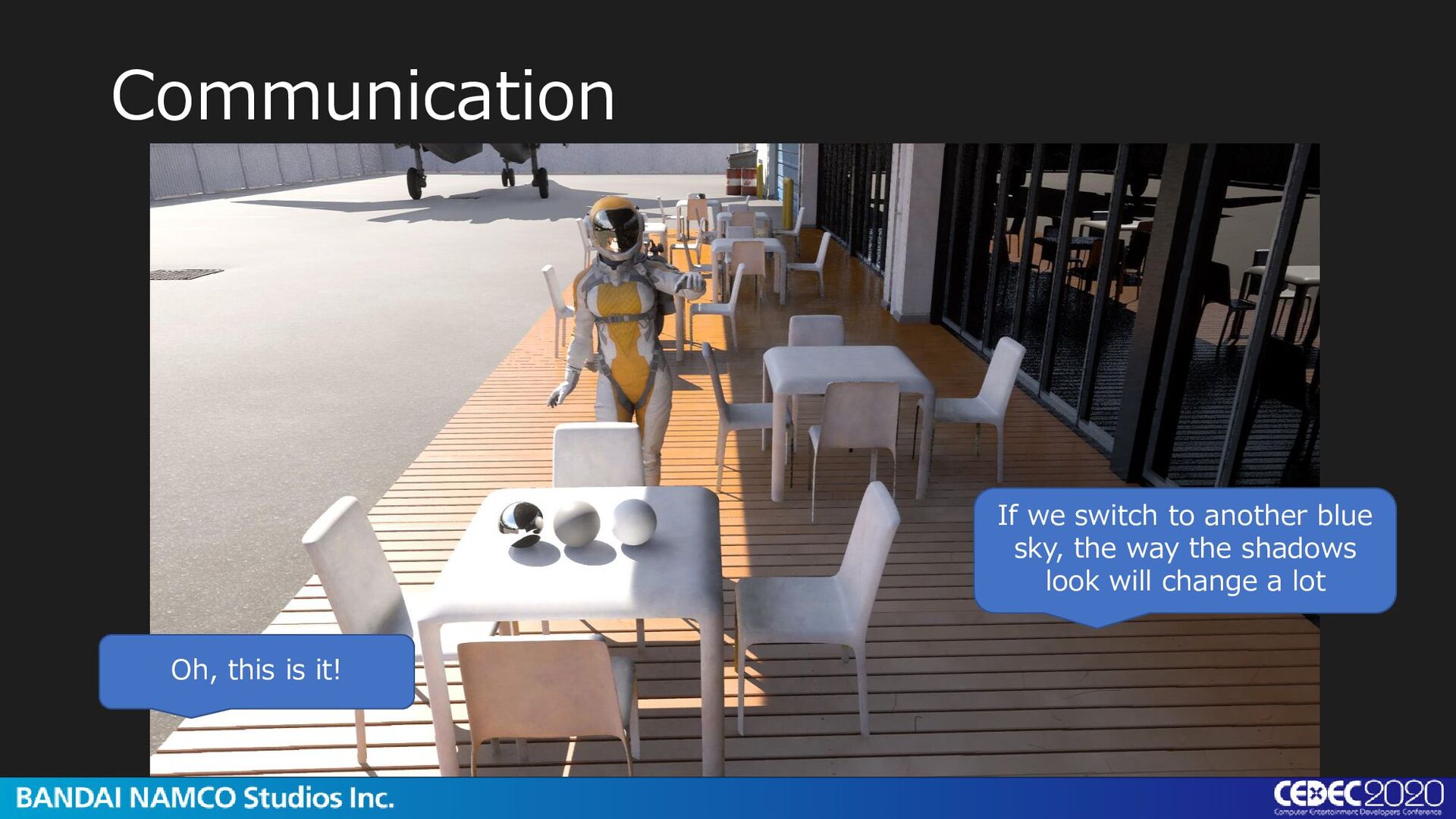
the asset or light, you can focus on the post-process work. This communication between developers revolves around the reliable axis of the look-dev environment, so things can progress smoothly
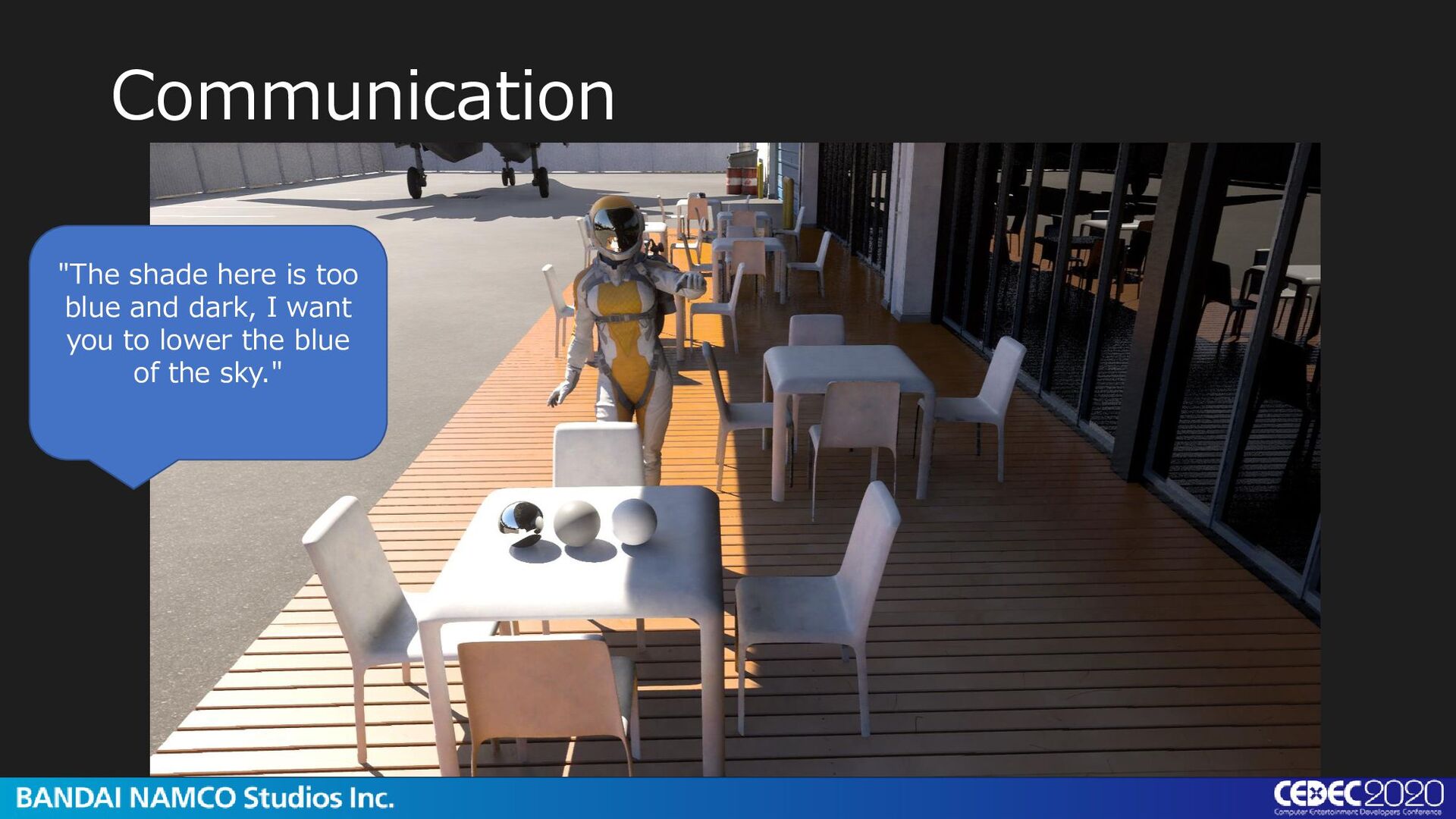
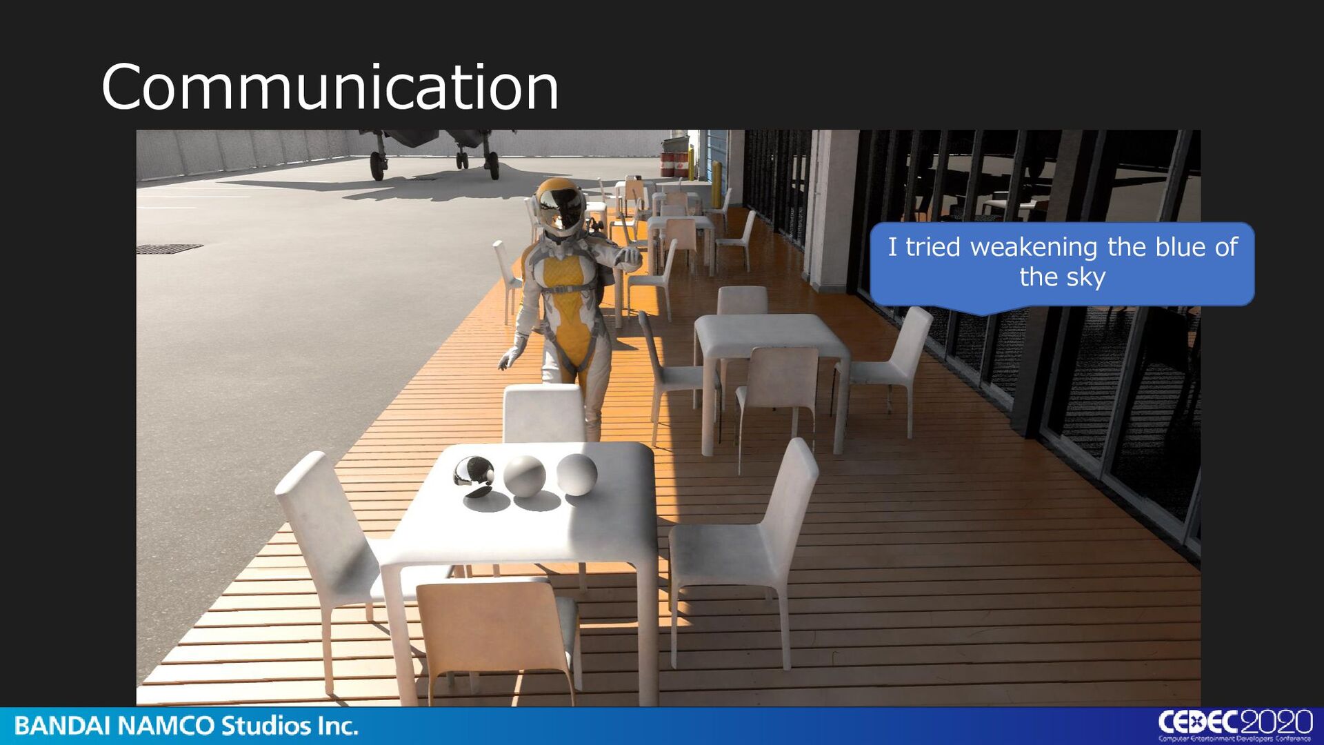
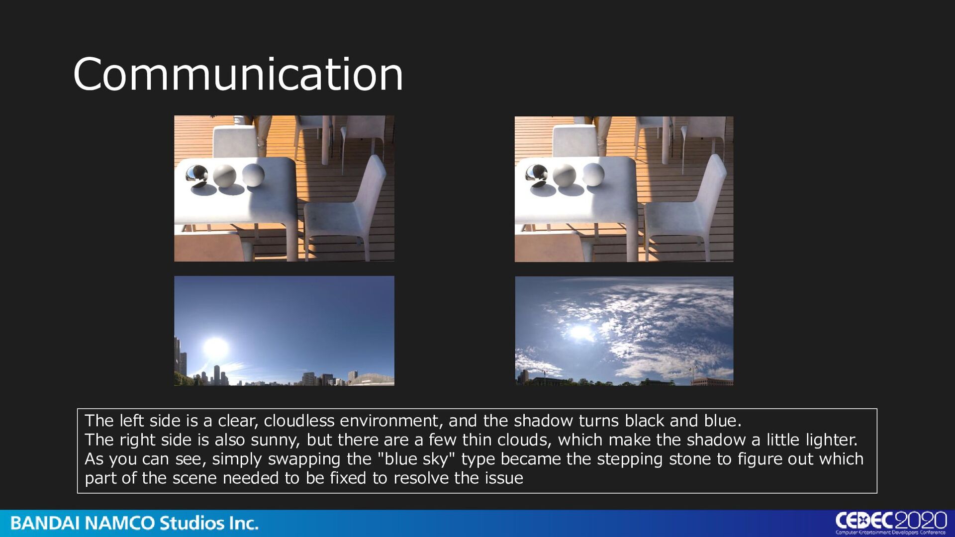
the shadow turns black and blue. The right side is also sunny, but there are a few thin clouds, which make the shadow a little lighter. As you can see, simply swapping the "blue sky" type became the stepping stone to figure out which part of the scene needed to be fixed to resolve the issue
way, we have given examples of the use of the TrueHDRI, but the fact that real light can be reproduced on the engine gives us a sense of security. I think TrueHDRI plays an important role in improving the reliability of the verification environment. There are many other ways to use it, but today I only talked about representative cases.
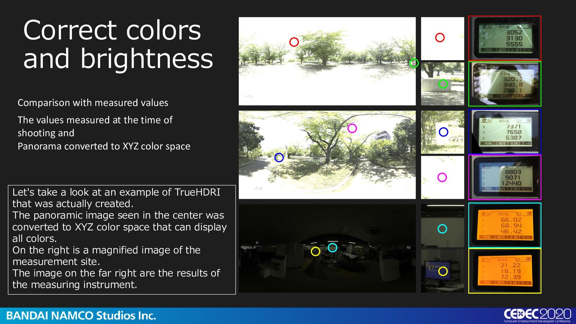
measured at the time of shooting and Panorama converted to XYZ color space Let's take a look at an example of TrueHDRI that was actually created. The panoramic image seen in the center was converted to XYZ color space that can display all colors. On the right is a magnified image of the measurement site. The image on the far right are the results of the measuring instrument.
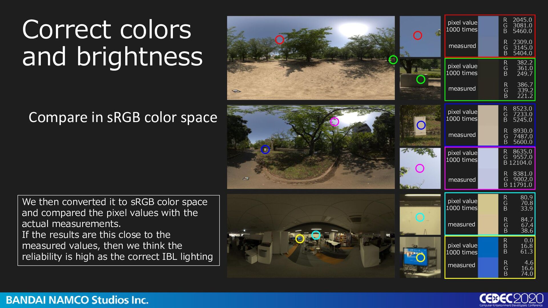
value 1000 times pixel value 1000 times pixel value 1000 times pixel value 1000 times pixel value 1000 times pixel value 1000 times measured measured measured measured measured measured We then converted it to sRGB color space and compared the pixel values with the actual measurements. If the results are this close to the measured values, then we think the reliability is high as the correct IBL lighting
comparison of renderings lit with TrueHDRI. We tested whether the IBL we shot was correct as the lighting reference. If the colors of the sun and the shade are the same, the colors of sky and the sun are correct.
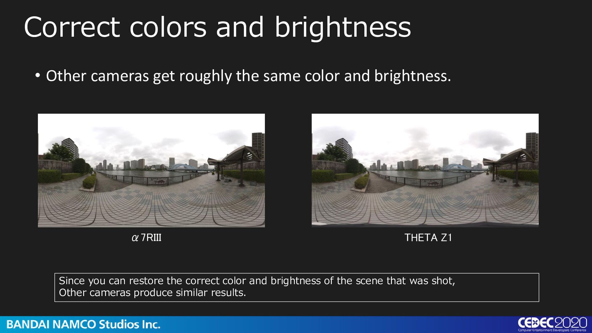
α7RIII THETA Z1 Correct colors and brightness Since you can restore the correct color and brightness of the scene that was shot, Other cameras produce similar results.
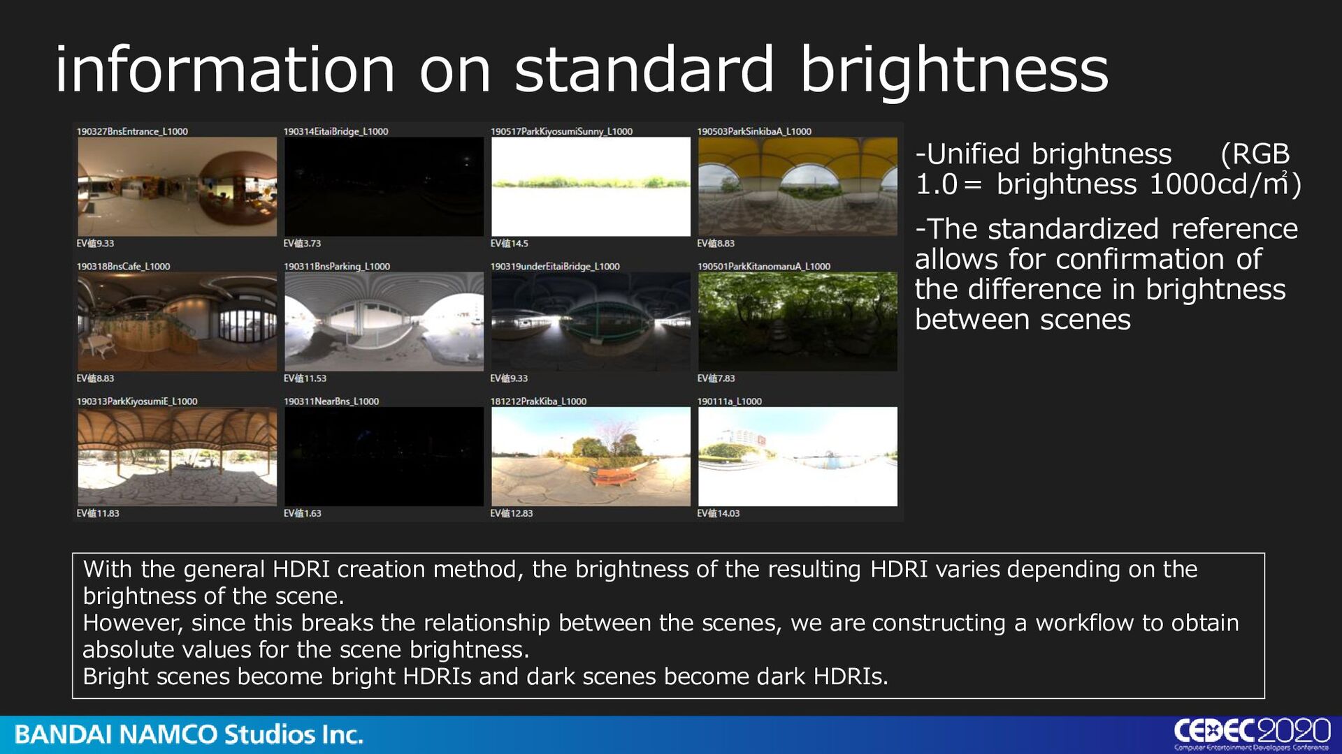
-The standardized reference allows for confirmation of the difference in brightness between scenes With the general HDRI creation method, the brightness of the resulting HDRI varies depending on the brightness of the scene. However, since this breaks the relationship between the scenes, we are constructing a workflow to obtain absolute values for the scene brightness. Bright scenes become bright HDRIs and dark scenes become dark HDRIs.
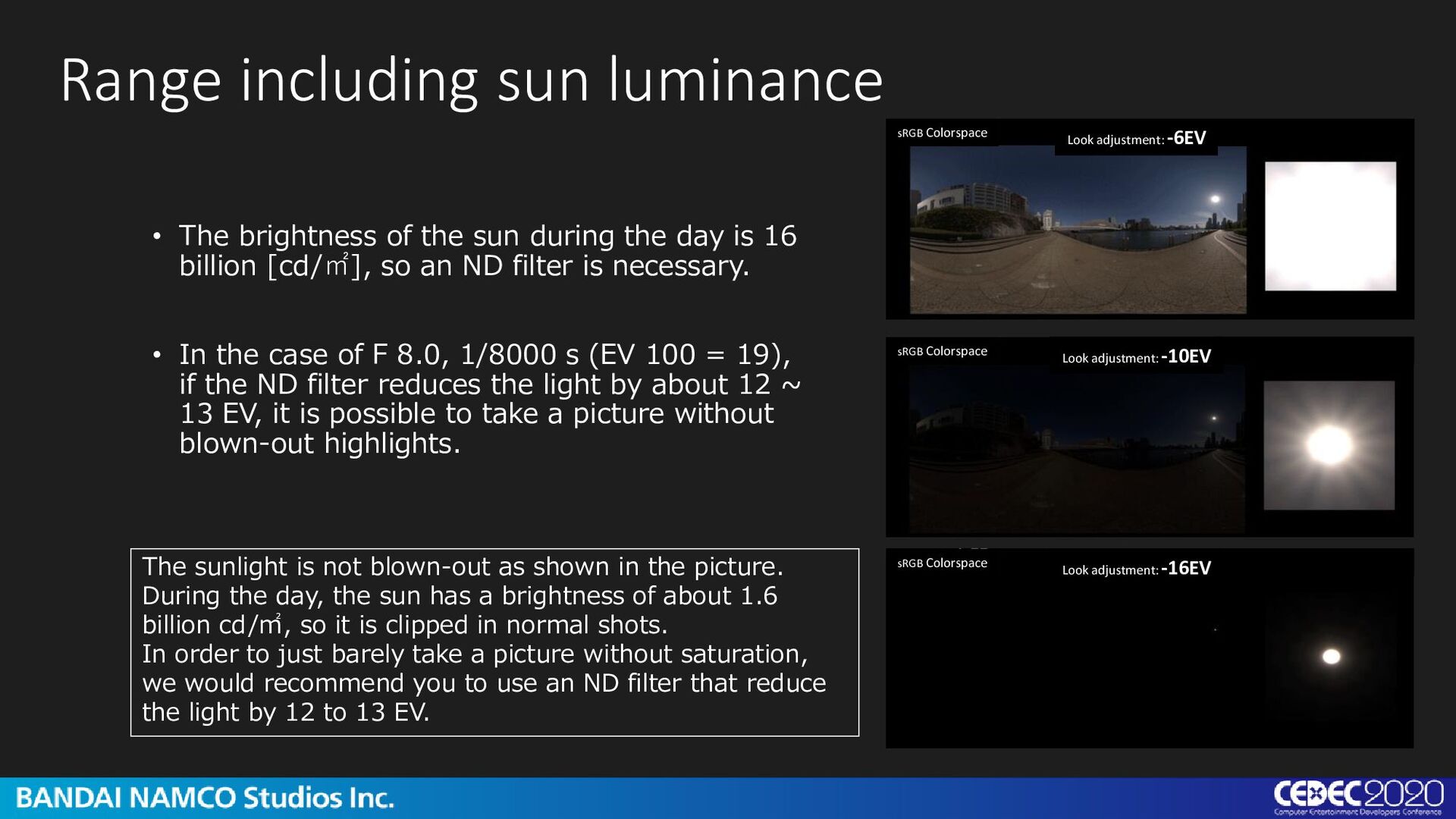
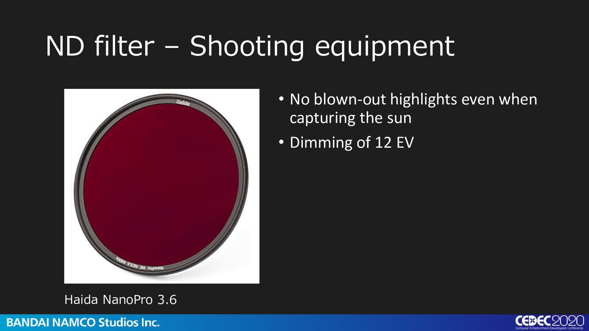
16 billion [cd/㎡], so an ND filter is necessary. • In the case of F 8.0, 1/8000 s (EV 100 = 19), if the ND filter reduces the light by about 12 ~ 13 EV, it is possible to take a picture without blown-out highlights. Range including sun luminance sRGB Colorspace sRGB Colorspace sRGB Colorspace Look adjustment: -6EV Look adjustment: -10EV Look adjustment: -16EV The sunlight is not blown-out as shown in the picture. During the day, the sun has a brightness of about 1.6 billion cd/㎡, so it is clipped in normal shots. In order to just barely take a picture without saturation, we would recommend you to use an ND filter that reduce the light by 12 to 13 EV.
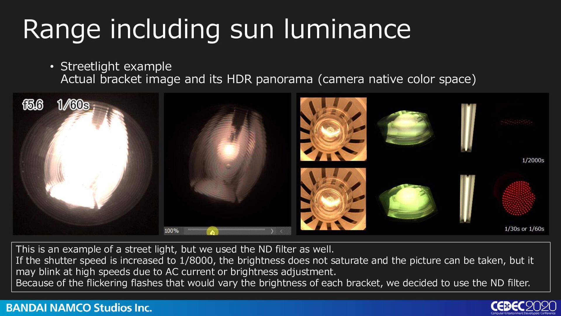
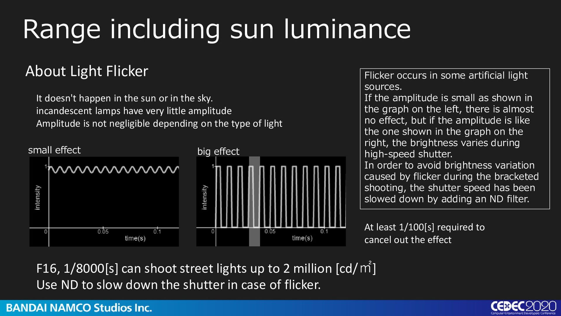
(camera native color space) Range including sun luminance This is an example of a street light, but we used the ND filter as well. If the shutter speed is increased to 1/8000, the brightness does not saturate and the picture can be taken, but it may blink at high speeds due to AC current or brightness adjustment. Because of the flickering flashes that would vary the brightness of each bracket, we decided to use the ND filter.
incandescent lamps have very little amplitude Amplitude is not negligible depending on the type of light Range including sun luminance About Light Flicker F16, 1/8000[s] can shoot street lights up to 2 million [cd/㎡] Use ND to slow down the shutter in case of flicker. small effect big effect At least 1/100[s] required to cancel out the effect Flicker occurs in some artificial light sources. If the amplitude is small as shown in the graph on the left, there is almost no effect, but if the amplitude is like the one shown in the graph on the right, the brightness varies during high-speed shutter. In order to avoid brightness variation caused by flicker during the bracketed shooting, the shutter speed has been slowed down by adding an ND filter.
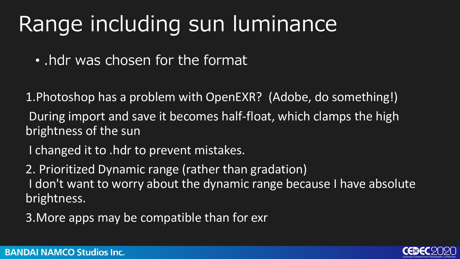
problem with OpenEXR? (Adobe, do something!) During import and save it becomes half-float, which clamps the high brightness of the sun I changed it to .hdr to prevent mistakes. 2. Prioritized Dynamic range (rather than gradation) I don't want to worry about the dynamic range because I have absolute brightness. 3.More apps may be compatible than for exr Range including sun luminance
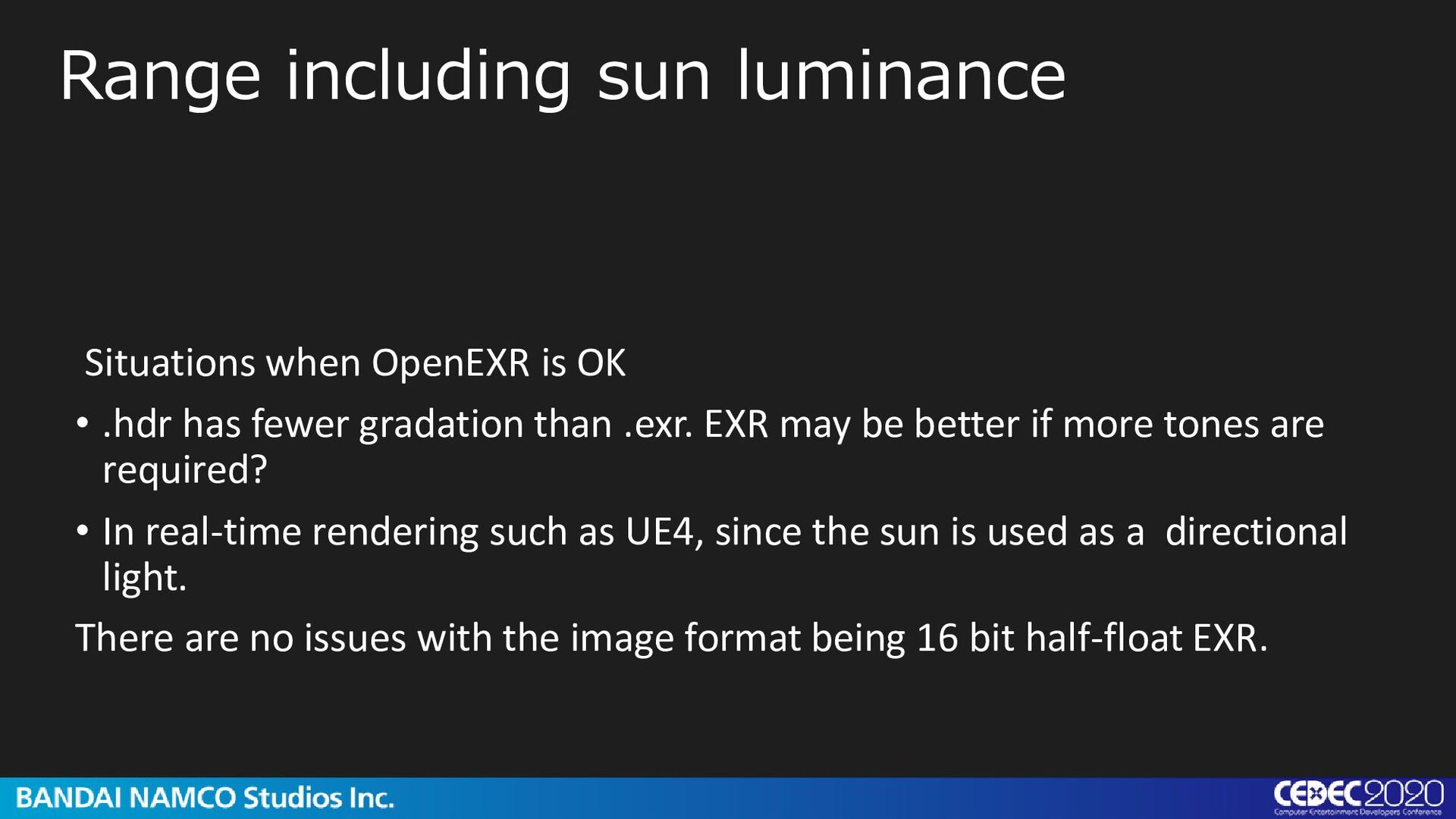
.hdr has fewer gradation than .exr. EXR may be better if more tones are required? • In real-time rendering such as UE4, since the sun is used as a directional light. There are no issues with the image format being 16 bit half-float EXR.
it brightly, you can see contrast-reducing haze all over the image. • Not much of a problem with IBL lighting Therefore, this situation has not been addressed. Range including sun luminance
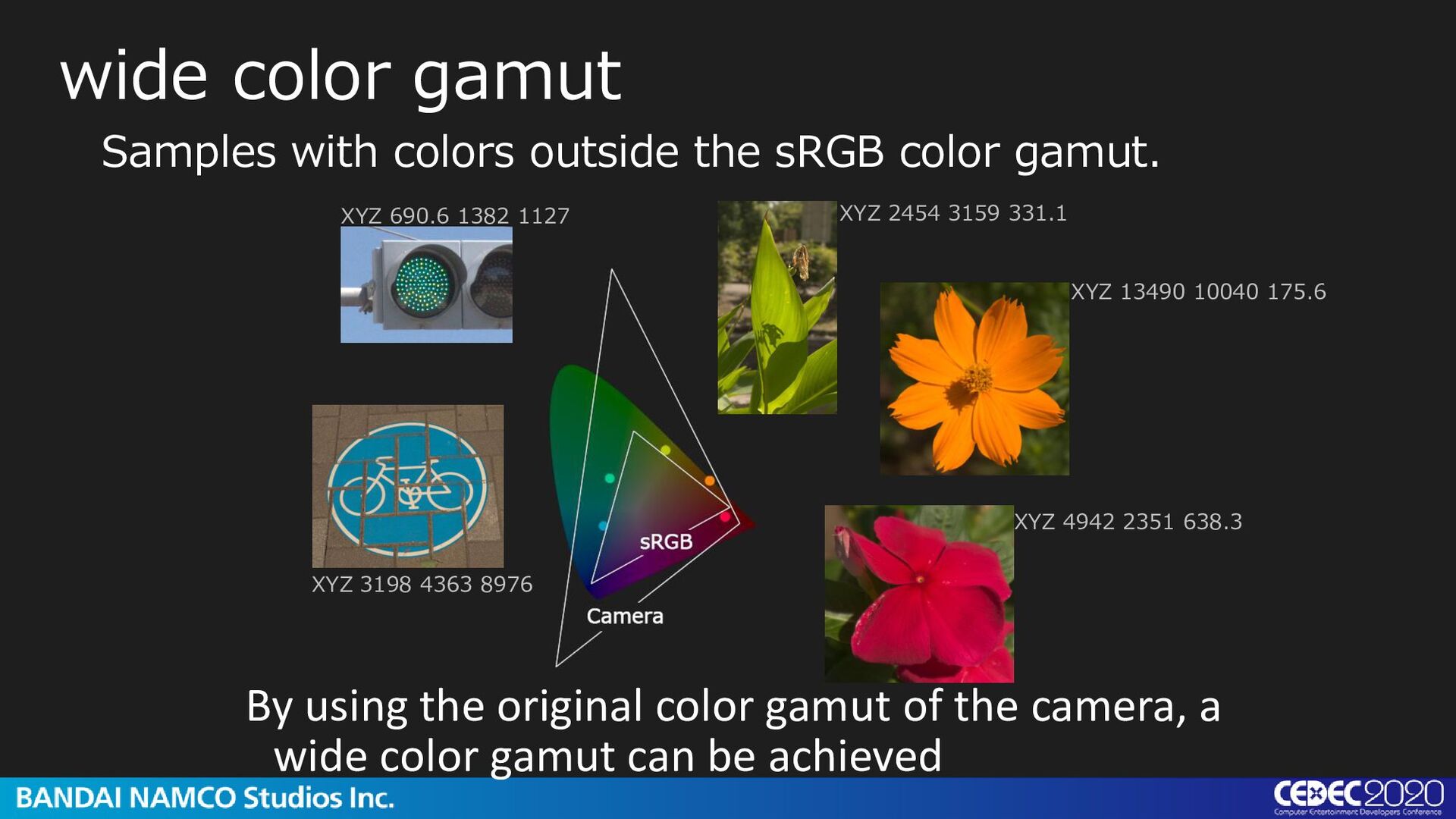
gamut By using the original color gamut of the camera, a wide color gamut can be achieved XYZ 2454 3159 331.1 XYZ 690.6 1382 1127 XYZ 3198 4363 8976 XYZ 13490 10040 175.6 XYZ 4942 2351 638.3
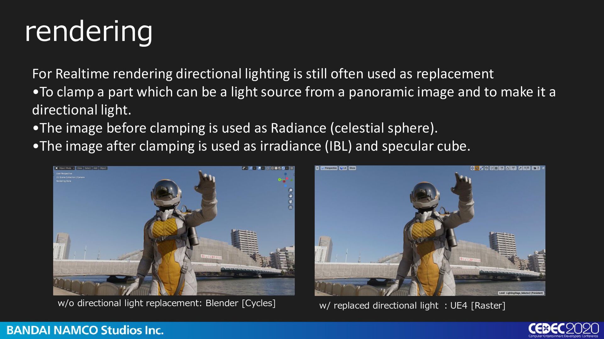
as replacement •To clamp a part which can be a light source from a panoramic image and to make it a directional light. •The image before clamping is used as Radiance (celestial sphere). •The image after clamping is used as irradiance (IBL) and specular cube. w/o directional light replacement: Blender [Cycles] w/ replaced directional light :UE4 [Raster]
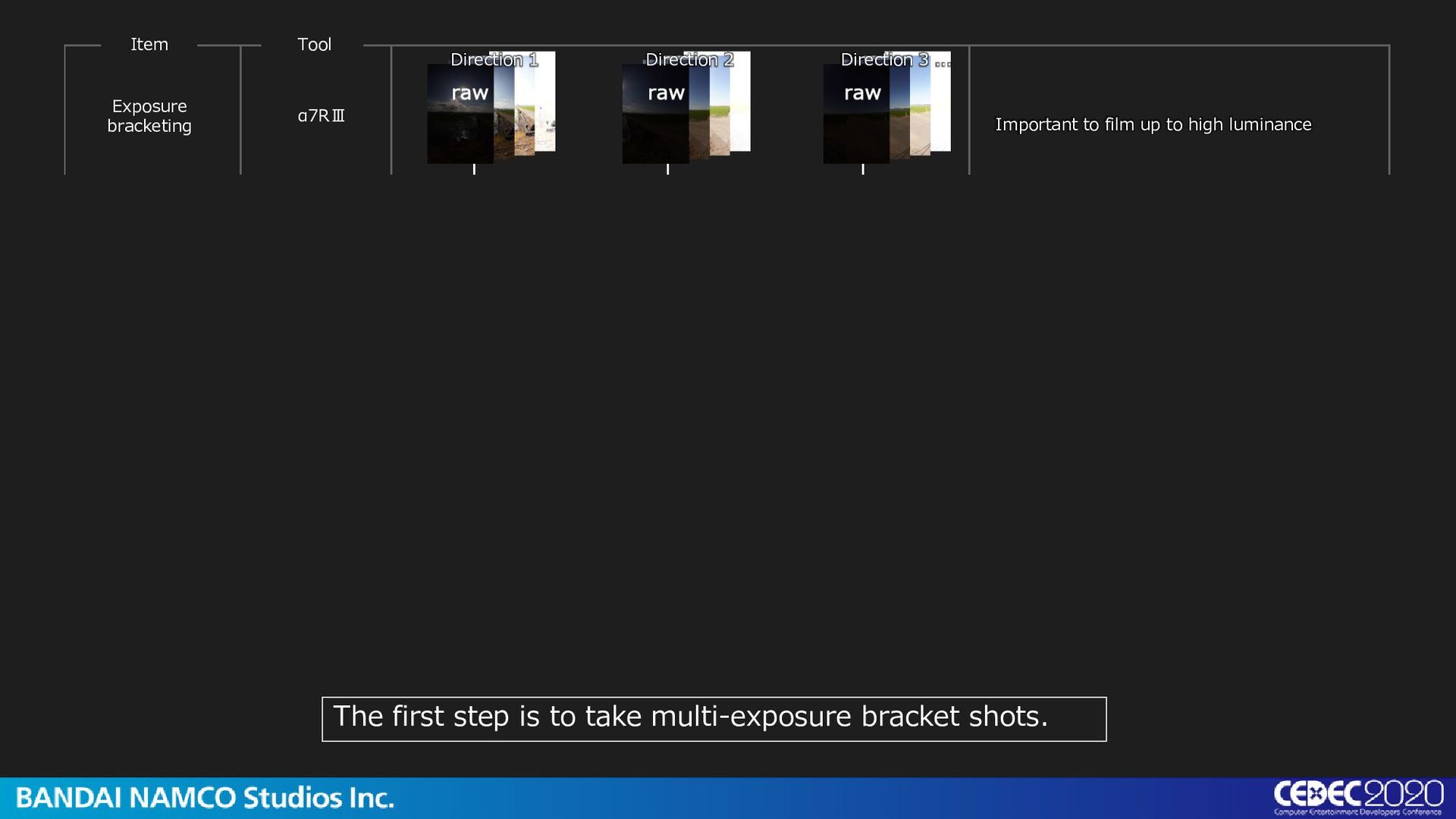
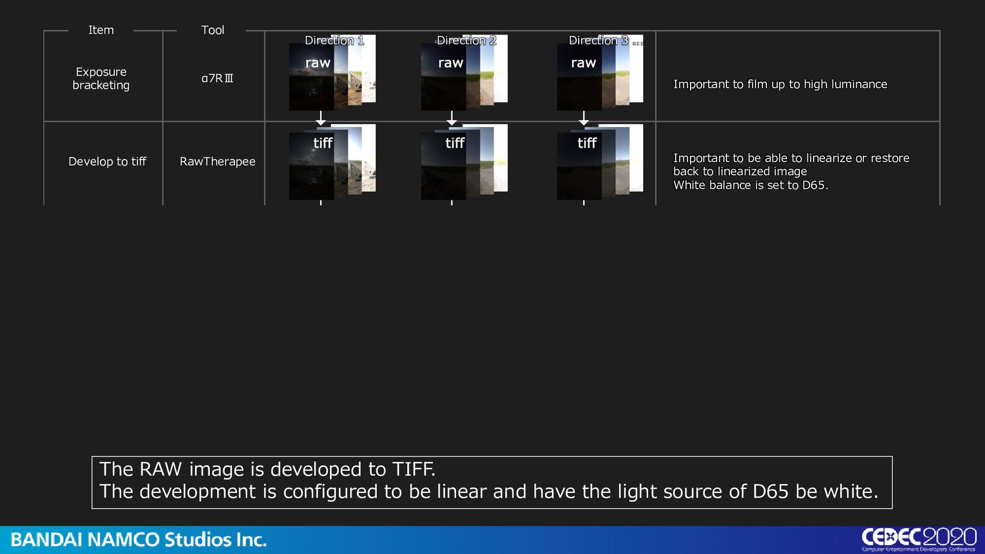
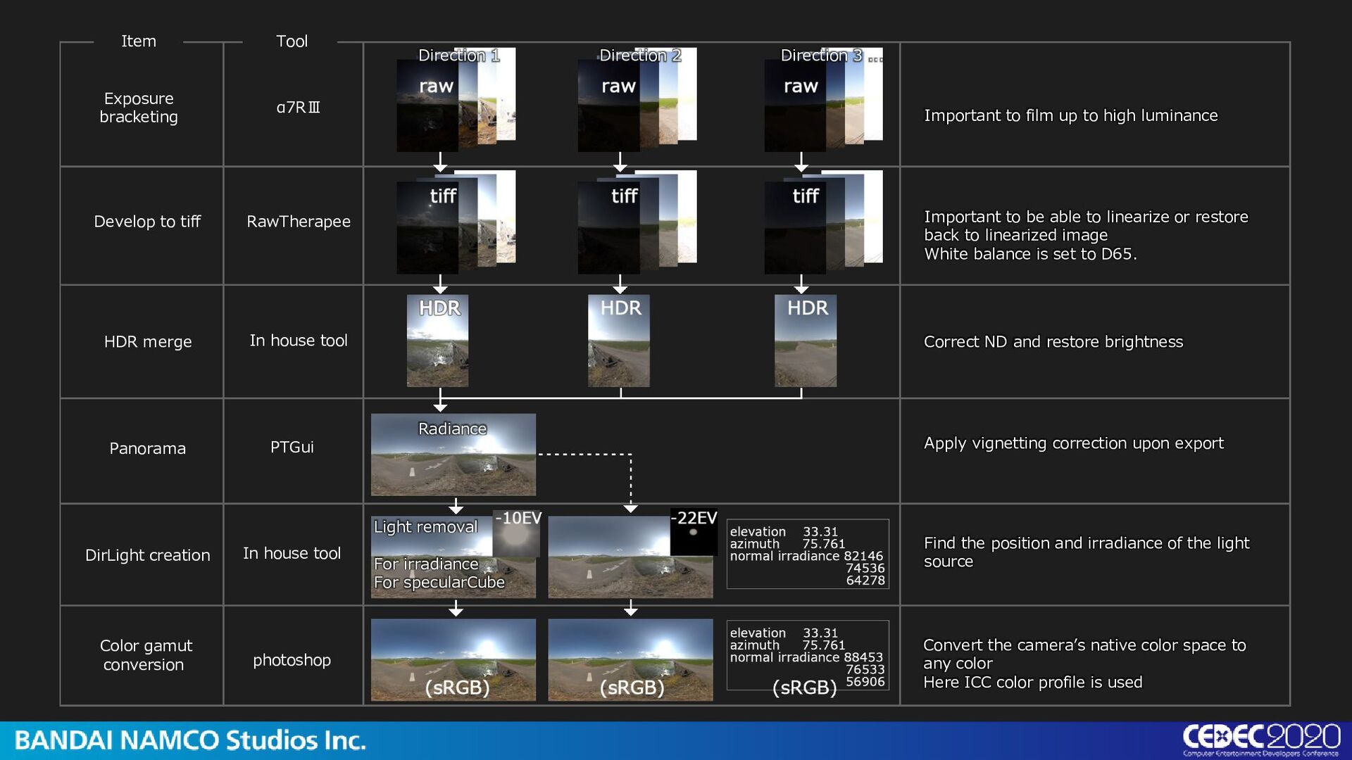
1 Direction 2 Direction 3 ... Important to film up to high luminance Important to be able to linearize or restore back to linearized image White balance is set to D65. The RAW image is developed to TIFF. The development is configured to be linear and have the light source of D65 be white.
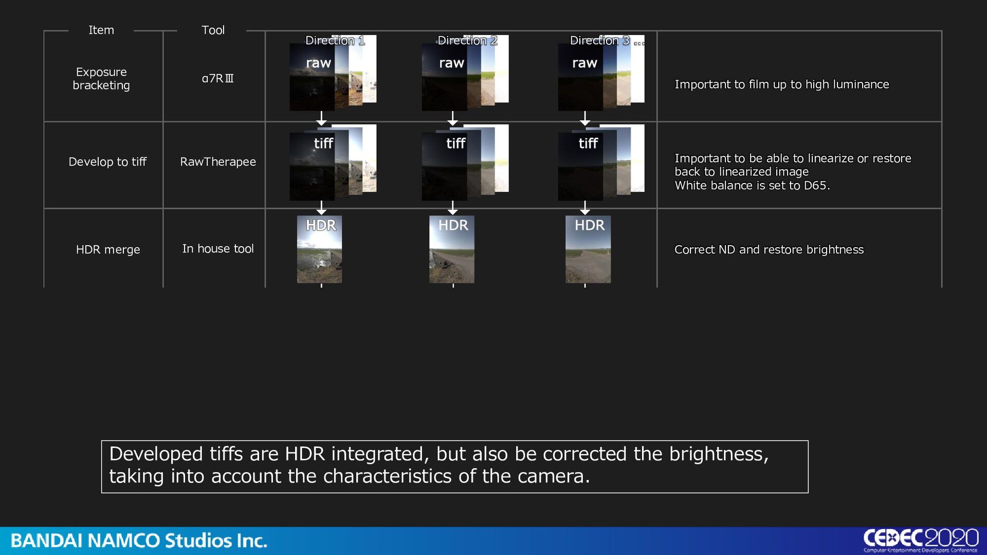
to tiff HDR merge Direction 1 Direction 2 Direction 3 ... Important to film up to high luminance Correct ND and restore brightness Developed tiffs are HDR integrated, but also be corrected the brightness, taking into account the characteristics of the camera. Important to be able to linearize or restore back to linearized image White balance is set to D65.
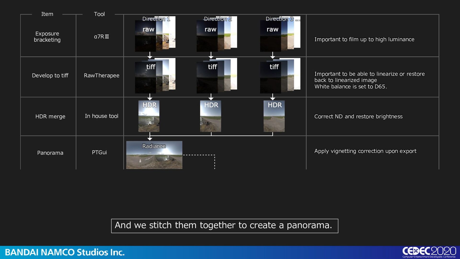
Develop to tiff HDR merge Panorama Direction 1 Direction 2 Direction 3 ... Radiance Important to film up to high luminance Correct ND and restore brightness Apply vignetting correction upon export And we stitch them together to create a panorama. Important to be able to linearize or restore back to linearized image White balance is set to D65.
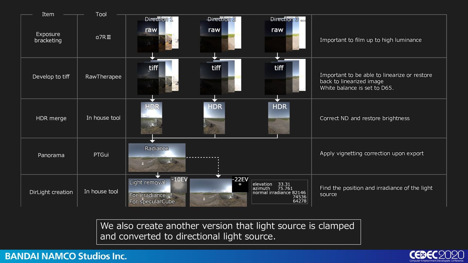
Develop to tiff HDR merge Panorama DirLight creation Direction 1 Direction 2 Direction 3 ... Light removal For irradiance For specularCube In house tool Important to film up to high luminance Correct ND and restore brightness Find the position and irradiance of the light source We also create another version that light source is clamped and converted to directional light source. Important to be able to linearize or restore back to linearized image White balance is set to D65. Radiance Apply vignetting correction upon export
photoshop Develop to tiff HDR merge Panorama DirLight creation Color gamut conversion Direction 1 Direction 2 Direction 3 ... Light removal For irradiance For specularCube In house tool Important to film up to high luminance Correct ND and restore brightness Find the position and irradiance of the light source Convert the camera’s native color space to any color Here ICC color profile is used Important to be able to linearize or restore back to linearized image White balance is set to D65. Radiance Apply vignetting correction upon export
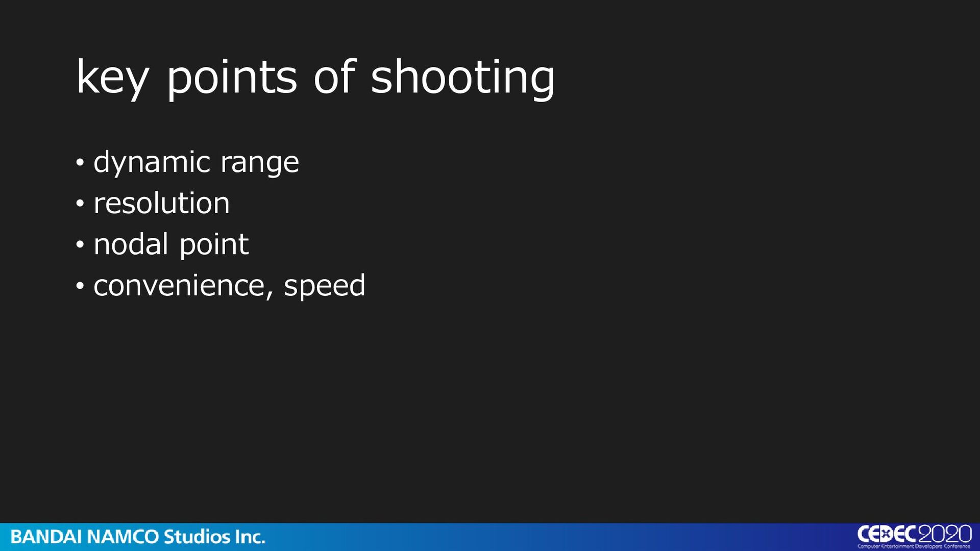
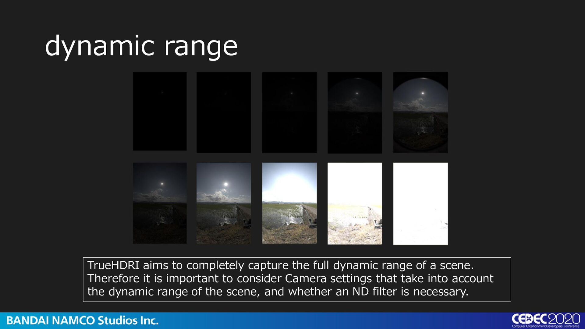
range of a scene. Therefore it is important to consider Camera settings that take into account the dynamic range of the scene, and whether an ND filter is necessary.
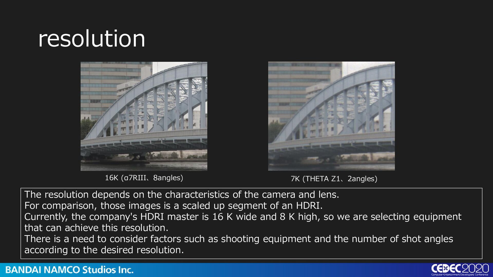
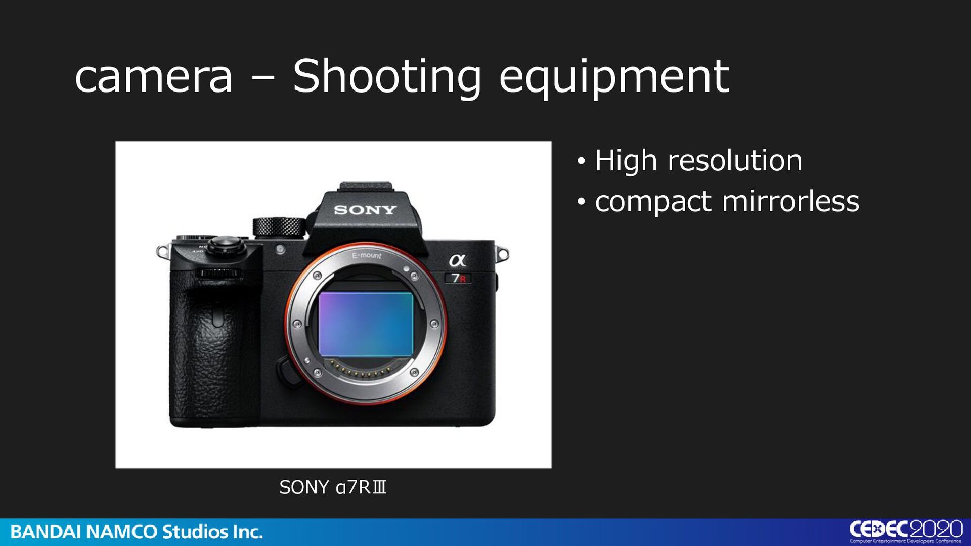
the characteristics of the camera and lens. For comparison, those images is a scaled up segment of an HDRI. Currently, the company's HDRI master is 16 K wide and 8 K high, so we are selecting equipment that can achieve this resolution. There is a need to consider factors such as shooting equipment and the number of shot angles according to the desired resolution.
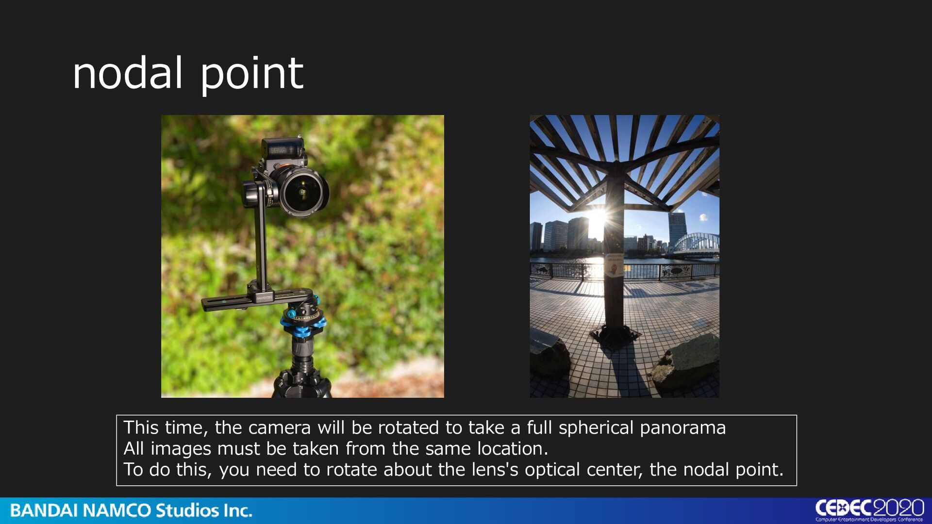
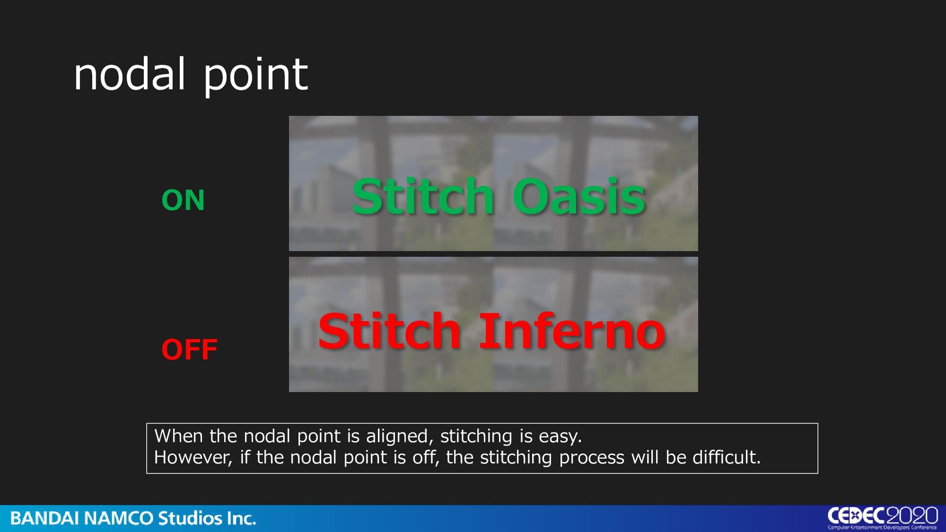
take a full spherical panorama All images must be taken from the same location. To do this, you need to rotate about the lens's optical center, the nodal point.
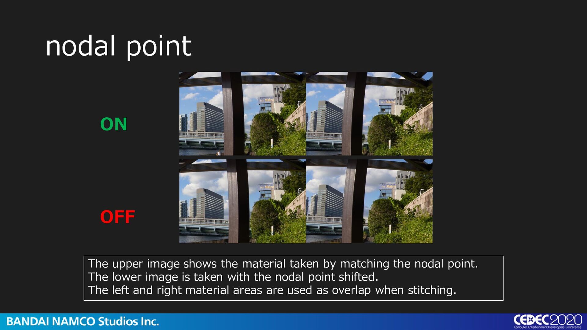
taken by matching the nodal point. The lower image is taken with the nodal point shifted. The left and right material areas are used as overlap when stitching.
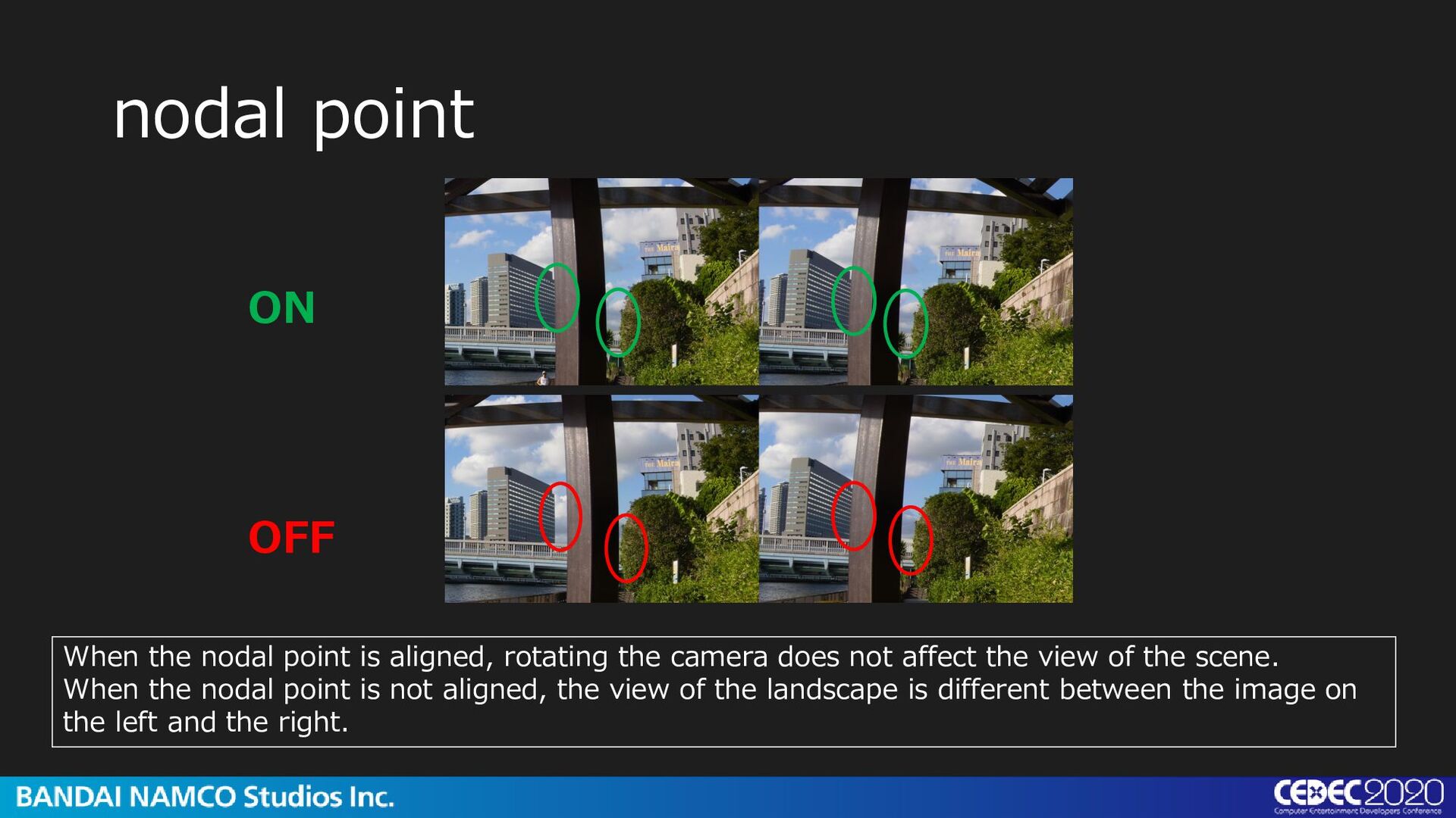
rotating the camera does not affect the view of the scene. When the nodal point is not aligned, the view of the landscape is different between the image on the left and the right.
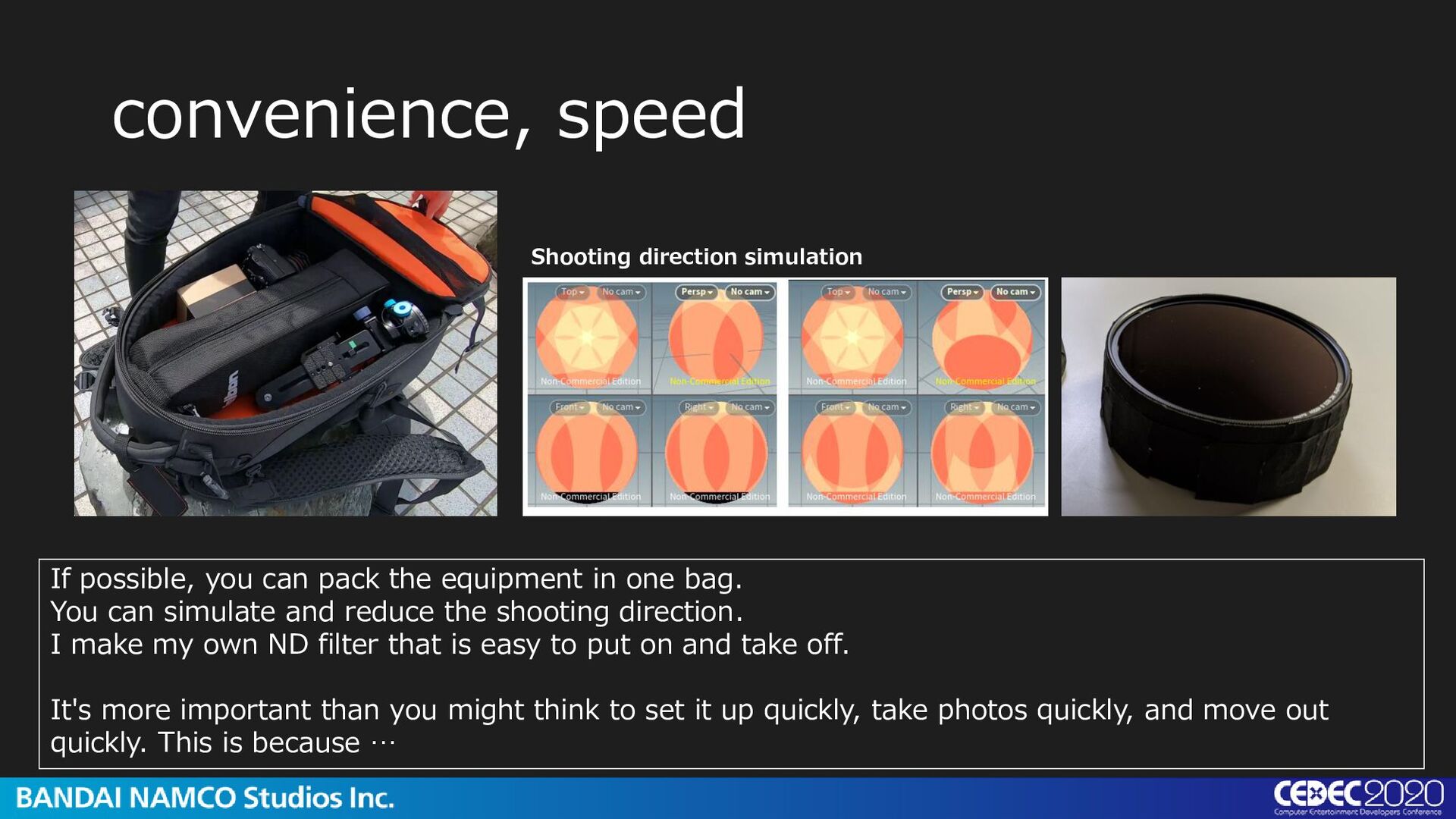
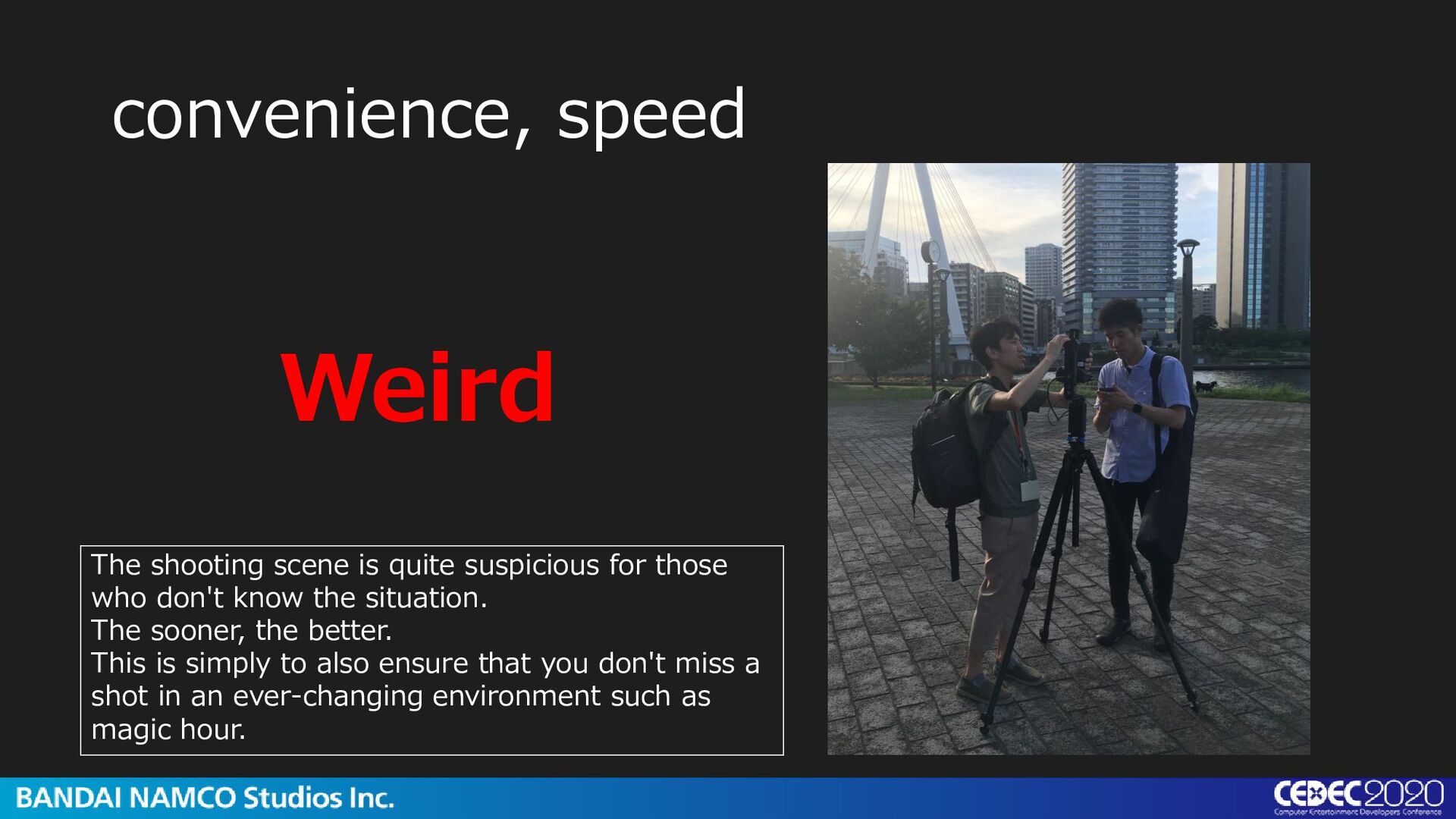
the equipment in one bag. You can simulate and reduce the shooting direction. I make my own ND filter that is easy to put on and take off. It's more important than you might think to set it up quickly, take photos quickly, and move out quickly. This is because …
those who don't know the situation. The sooner, the better. This is simply to also ensure that you don't miss a shot in an ever-changing environment such as magic hour.
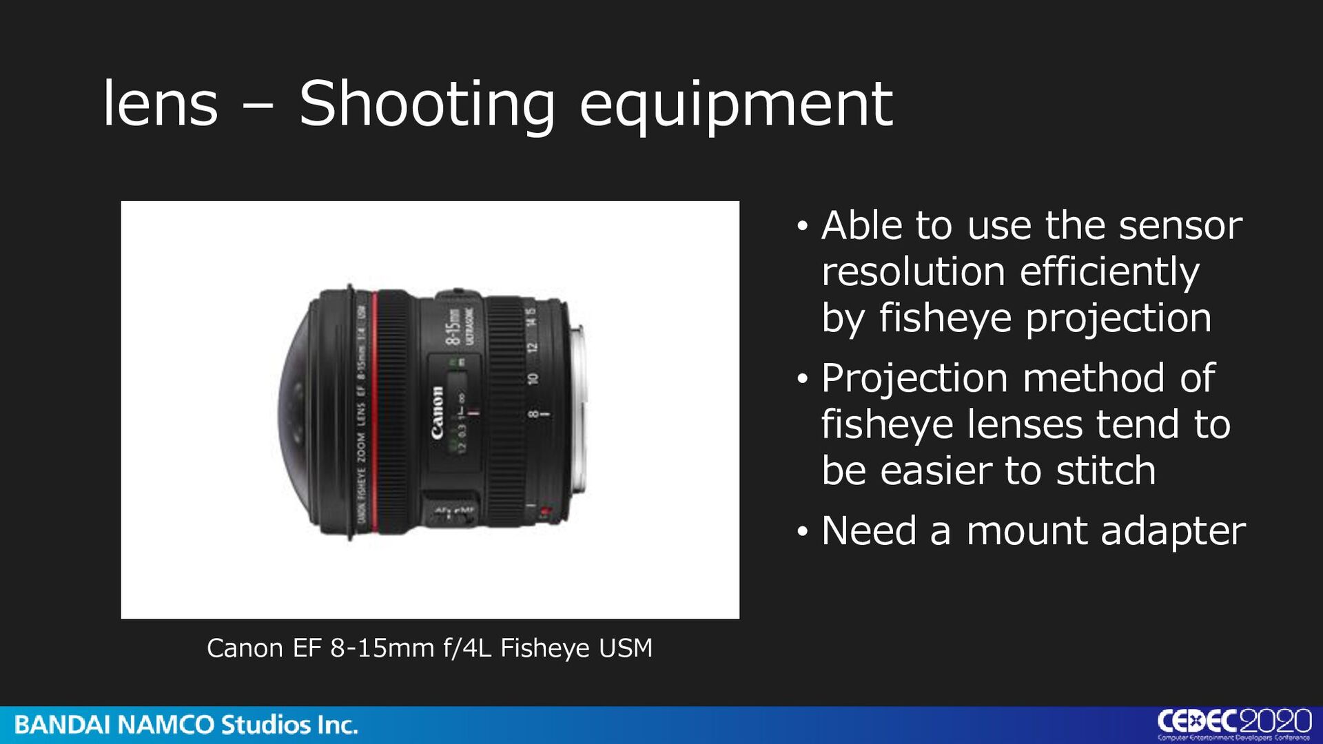
resolution efficiently by fisheye projection • Projection method of fisheye lenses tend to be easier to stitch • Need a mount adapter Canon EF 8-15mm f/4L Fisheye USM
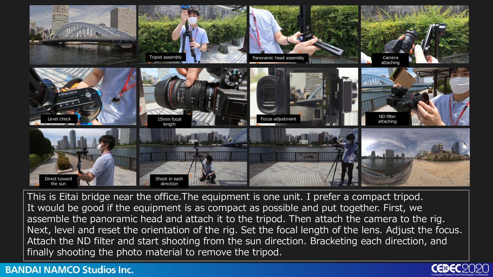
focal length Focus adjustment ND filter attaching Direct toward the sun Shoot in each direction This is Eitai bridge near the office.The equipment is one unit. I prefer a compact tripod. It would be good if the equipment is as compact as possible and put together. First, we assemble the panoramic head and attach it to the tripod. Then attach the camera to the rig. Next, level and reset the orientation of the rig. Set the focal length of the lens. Adjust the focus. Attach the ND filter and start shooting from the sun direction. Bracketing each direction, and finally shooting the photo material to remove the tripod.
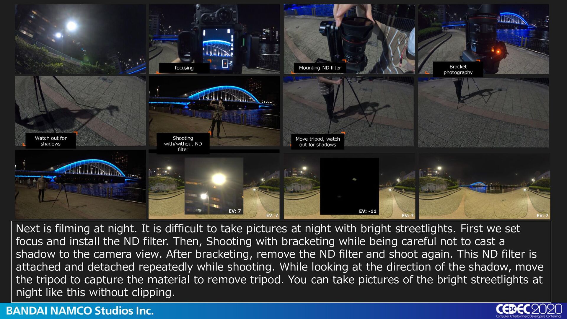
Shooting with/without ND filter Move tripod, watch out for shadows Next is filming at night. It is difficult to take pictures at night with bright streetlights. First we set focus and install the ND filter. Then, Shooting with bracketing while being careful not to cast a shadow to the camera view. After bracketing, remove the ND filter and shoot again. This ND filter is attached and detached repeatedly while shooting. While looking at the direction of the shadow, move the tripod to capture the material to remove tripod. You can take pictures of the bright streetlights at night like this without clipping.
The sun shooting with ND filter • F8.0 • ISO 100 • night • 1/400~10s bracket 5 bracket 3EV *alterations based on situation • omni-directional shooting with and without ND filter *excluding the part directly below the areas without visible light source • F4.0 *Shutter speed priorities over sharpness of picture • ISO 100
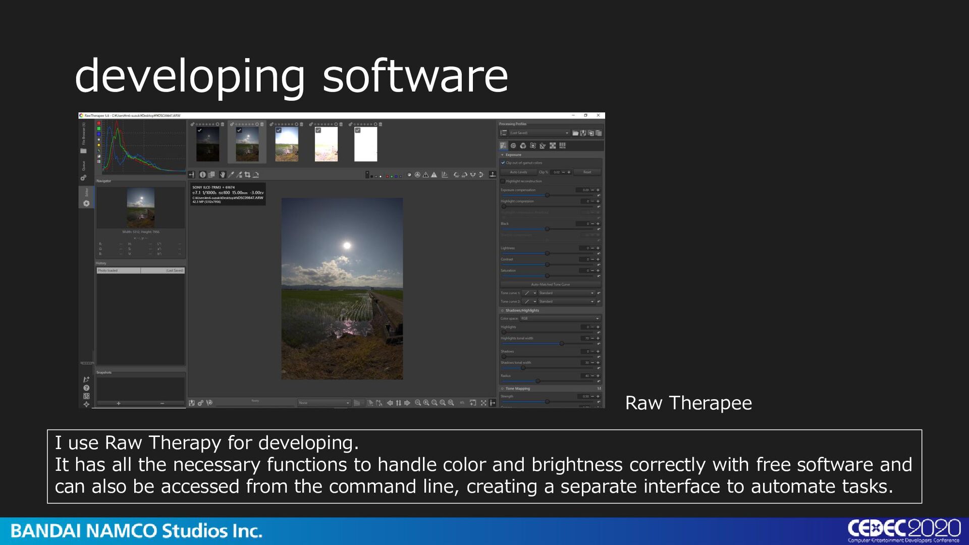
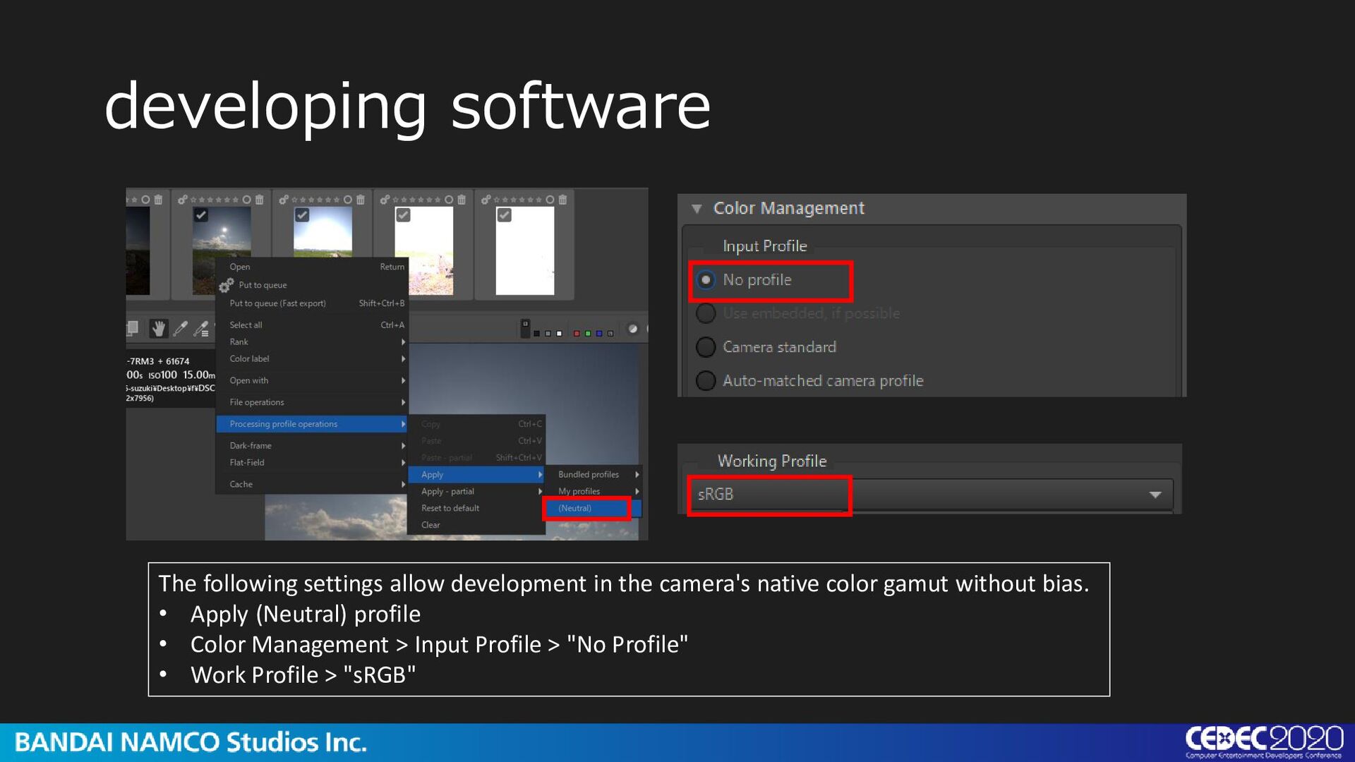
It has all the necessary functions to handle color and brightness correctly with free software and can also be accessed from the command line, creating a separate interface to automate tasks.
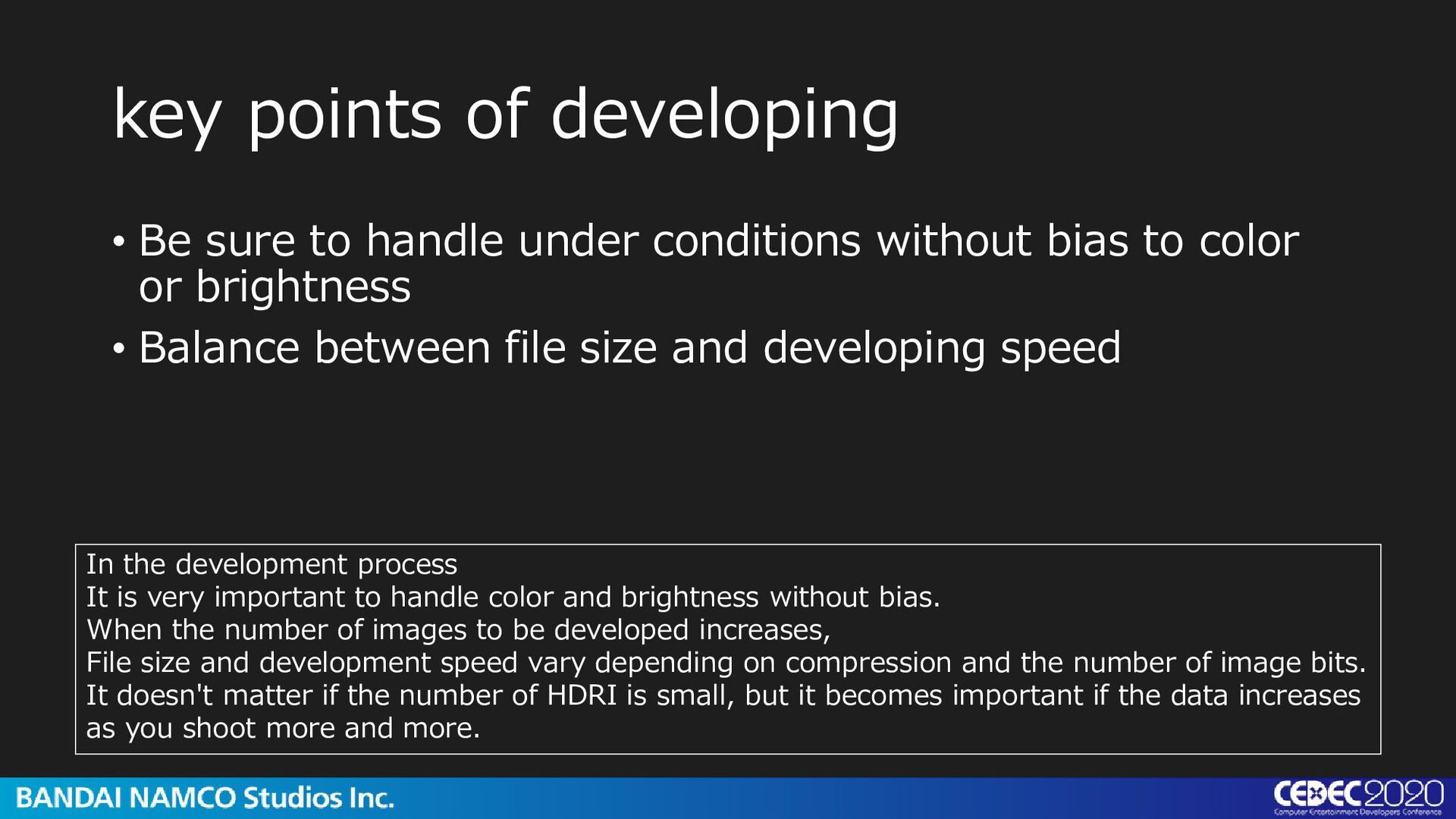
conditions without bias to color or brightness • Balance between file size and developing speed In the development process It is very important to handle color and brightness without bias. When the number of images to be developed increases, File size and development speed vary depending on compression and the number of image bits. It doesn't matter if the number of HDRI is small, but it becomes important if the data increases as you shoot more and more.
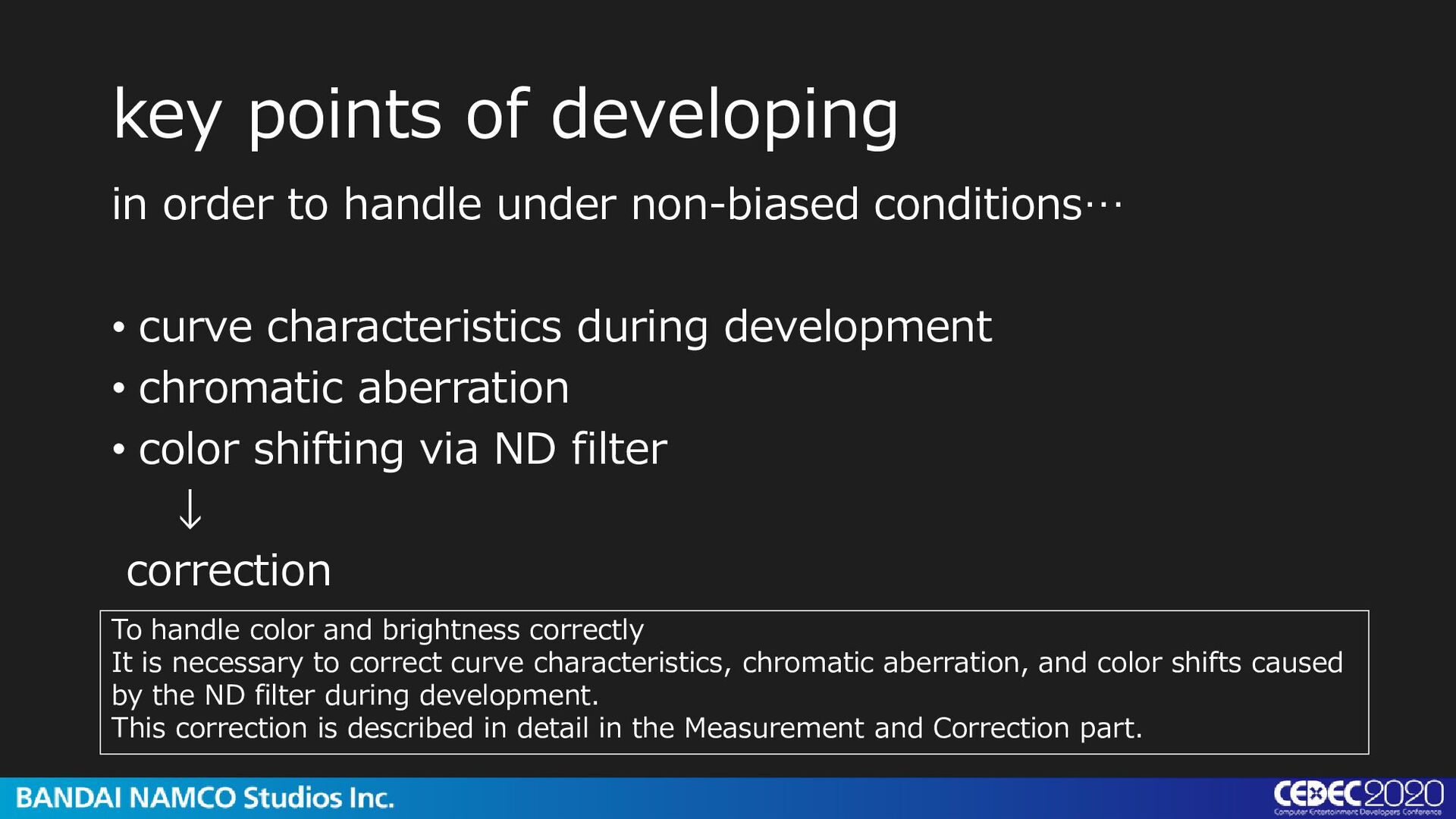
conditions… • curve characteristics during development • chromatic aberration • color shifting via ND filter ↓ correction To handle color and brightness correctly It is necessary to correct curve characteristics, chromatic aberration, and color shifts caused by the ND filter during development. This correction is described in detail in the Measurement and Correction part.
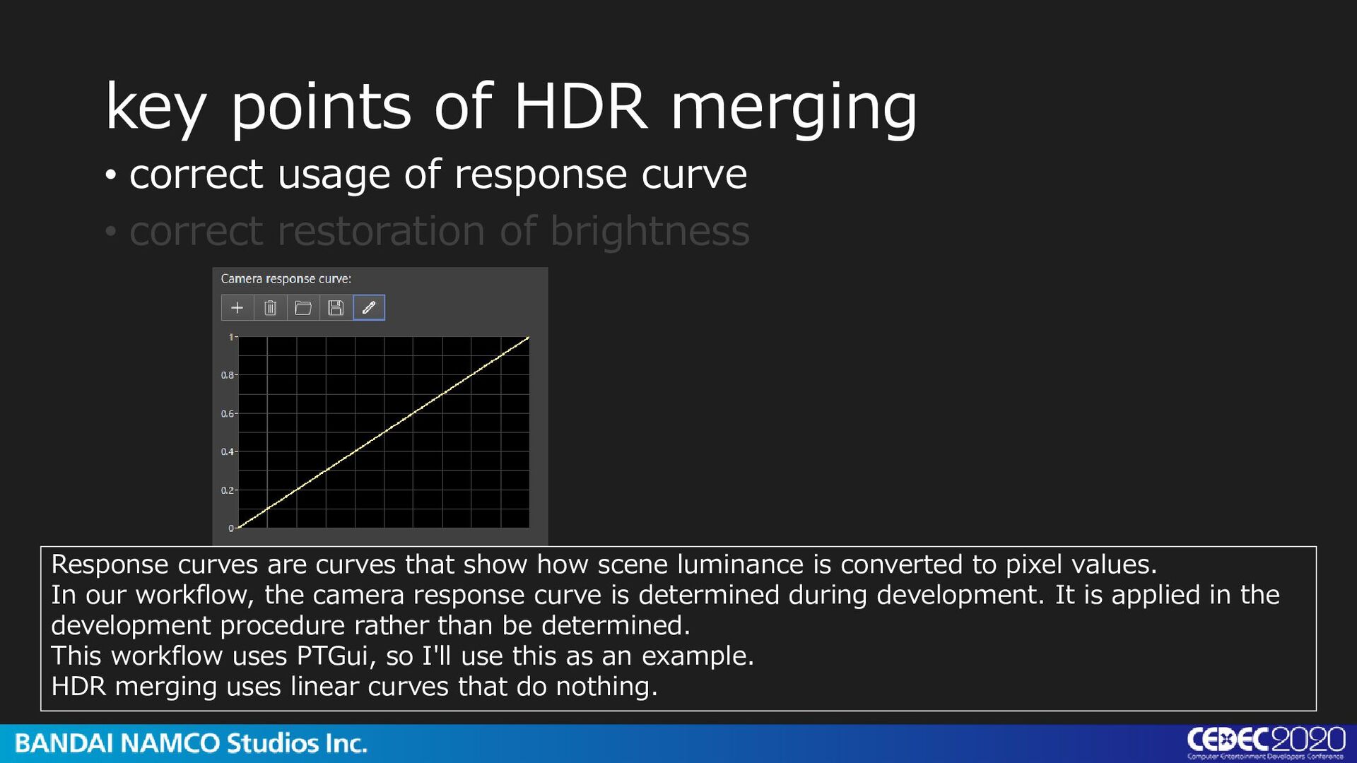
show how scene luminance is converted to pixel values. In our workflow, the camera response curve is determined during development. It is applied in the development procedure rather than be determined. This workflow uses PTGui, so I'll use this as an example. HDR merging uses linear curves that do nothing. • correct usage of response curve • correct restoration of brightness
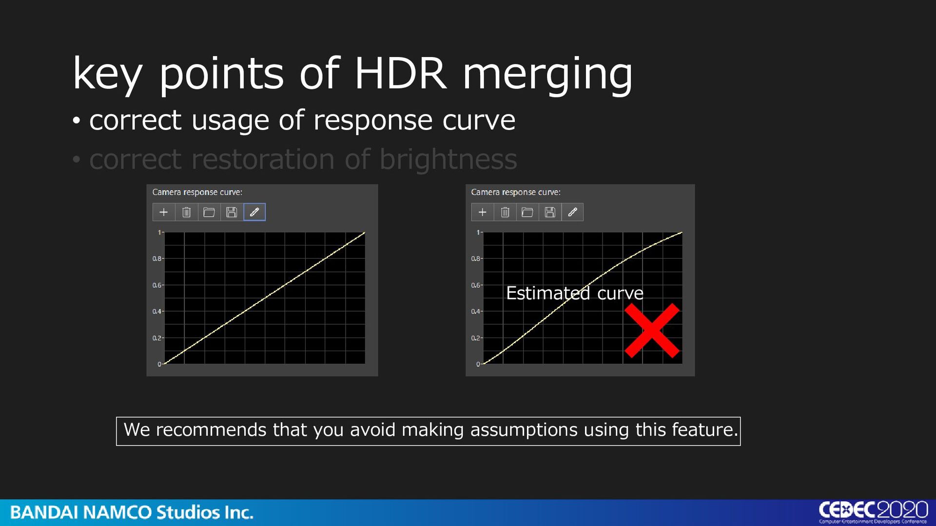
curve • correct restoration of brightness Estimated curve Software with HDR merging features like PTGui has a function to estimate the response curve when it is unknown. If you already know the response curve …
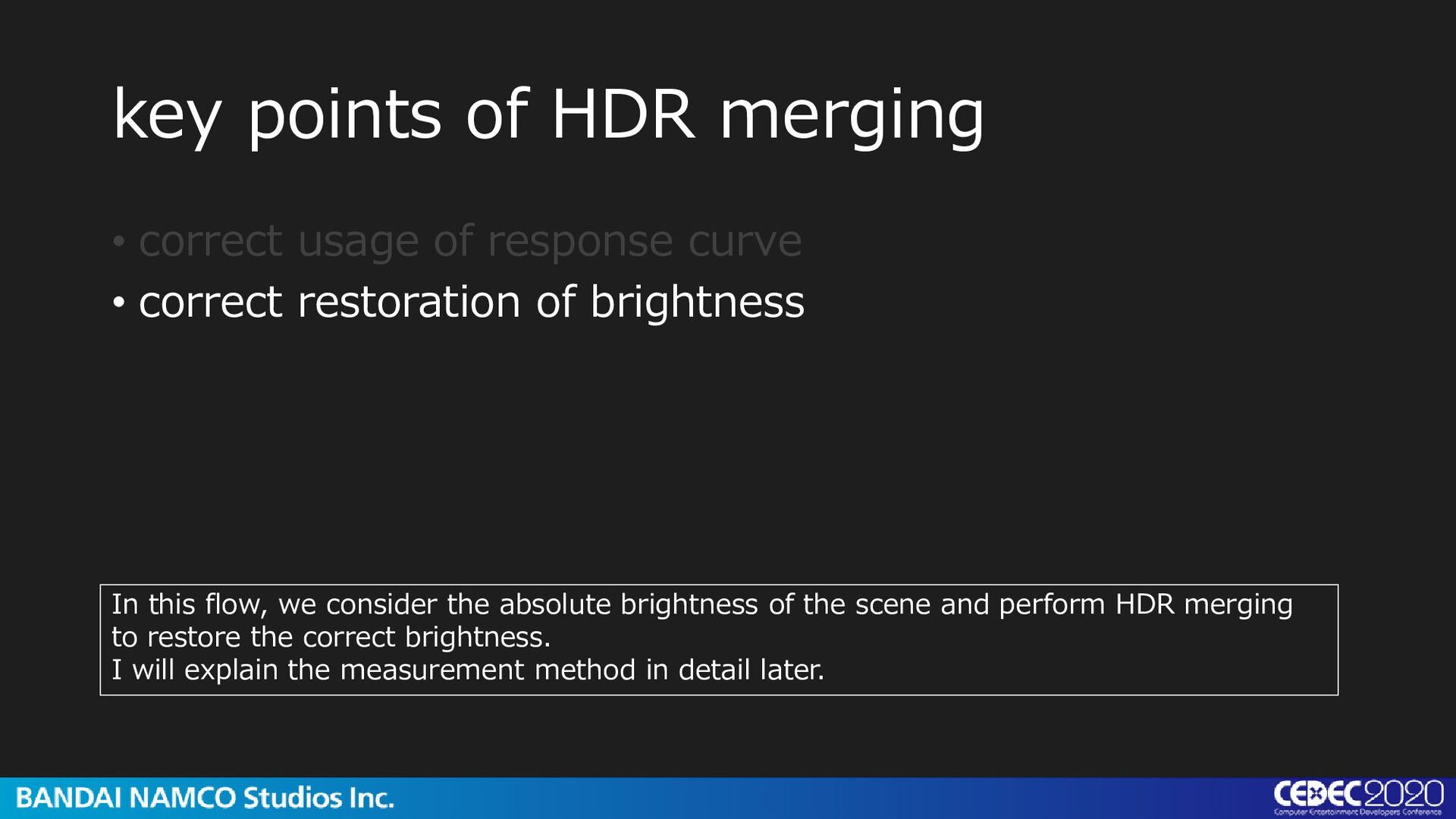
curve • correct restoration of brightness In this flow, we consider the absolute brightness of the scene and perform HDR merging to restore the correct brightness. I will explain the measurement method in detail later.
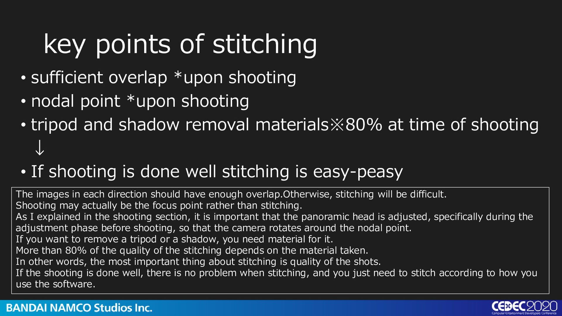
nodal point *upon shooting • tripod and shadow removal materials※80% at time of shooting ↓ • If shooting is done well stitching is easy-peasy The images in each direction should have enough overlap.Otherwise, stitching will be difficult. Shooting may actually be the focus point rather than stitching. As I explained in the shooting section, it is important that the panoramic head is adjusted, specifically during the adjustment phase before shooting, so that the camera rotates around the nodal point. If you want to remove a tripod or a shadow, you need material for it. More than 80% of the quality of the stitching depends on the material taken. In other words, the most important thing about stitching is quality of the shots. If the shooting is done well, there is no problem when stitching, and you just need to stitch according to how you use the software.
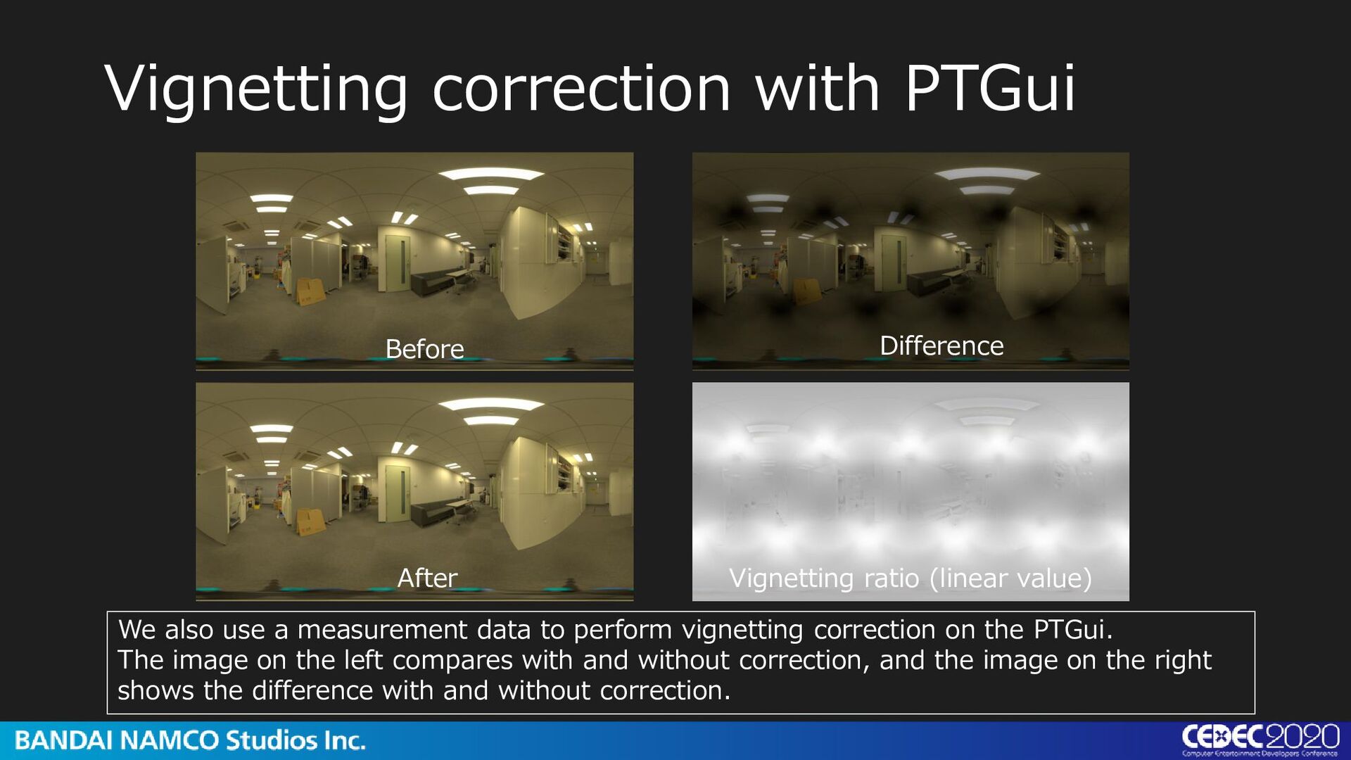
value) We also use a measurement data to perform vignetting correction on the PTGui. The image on the left compares with and without correction, and the image on the right shows the difference with and without correction.
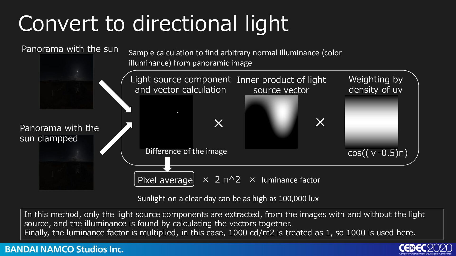
the sun clampped Light source component and vector calculation Inner product of light source vector Weighting by density of uv × 2 π^2 × luminance factor Difference of the image cos((v-0.5)π) × × Pixel average Sunlight on a clear day can be as high as 100,000 lux Sample calculation to find arbitrary normal illuminance (color illuminance) from panoramic image In this method, only the light source components are extracted, from the images with and without the light source, and the illuminance is found by calculating the vectors together. Finally, the luminance factor is multiplied, in this case, 1000 cd/m2 is treated as 1, so 1000 is used here.
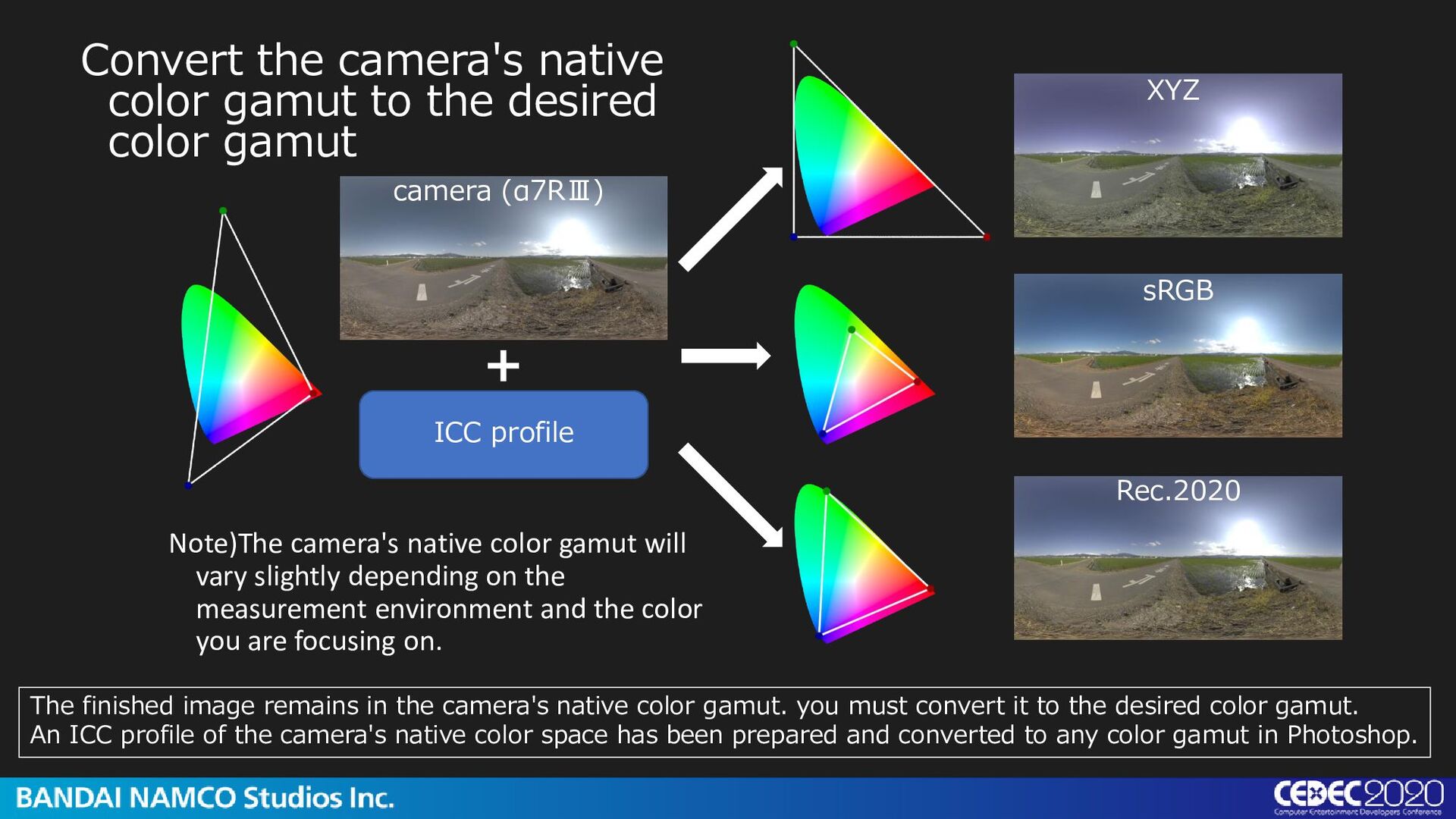
gamut camera (α7RⅢ) XYZ sRGB Rec.2020 Note)The camera's native color gamut will vary slightly depending on the measurement environment and the color you are focusing on. ICC profile + The finished image remains in the camera's native color gamut. you must convert it to the desired color gamut. An ICC profile of the camera's native color space has been prepared and converted to any color gamut in Photoshop.
seen, it is important to balance between the accuracy of the resulting HDRI and the ease with which it can be made. We will continue to improve the accuracy and optimize the method. We've talked a lot about correction in the previous slides. Now we explain how we measure and apply the data.
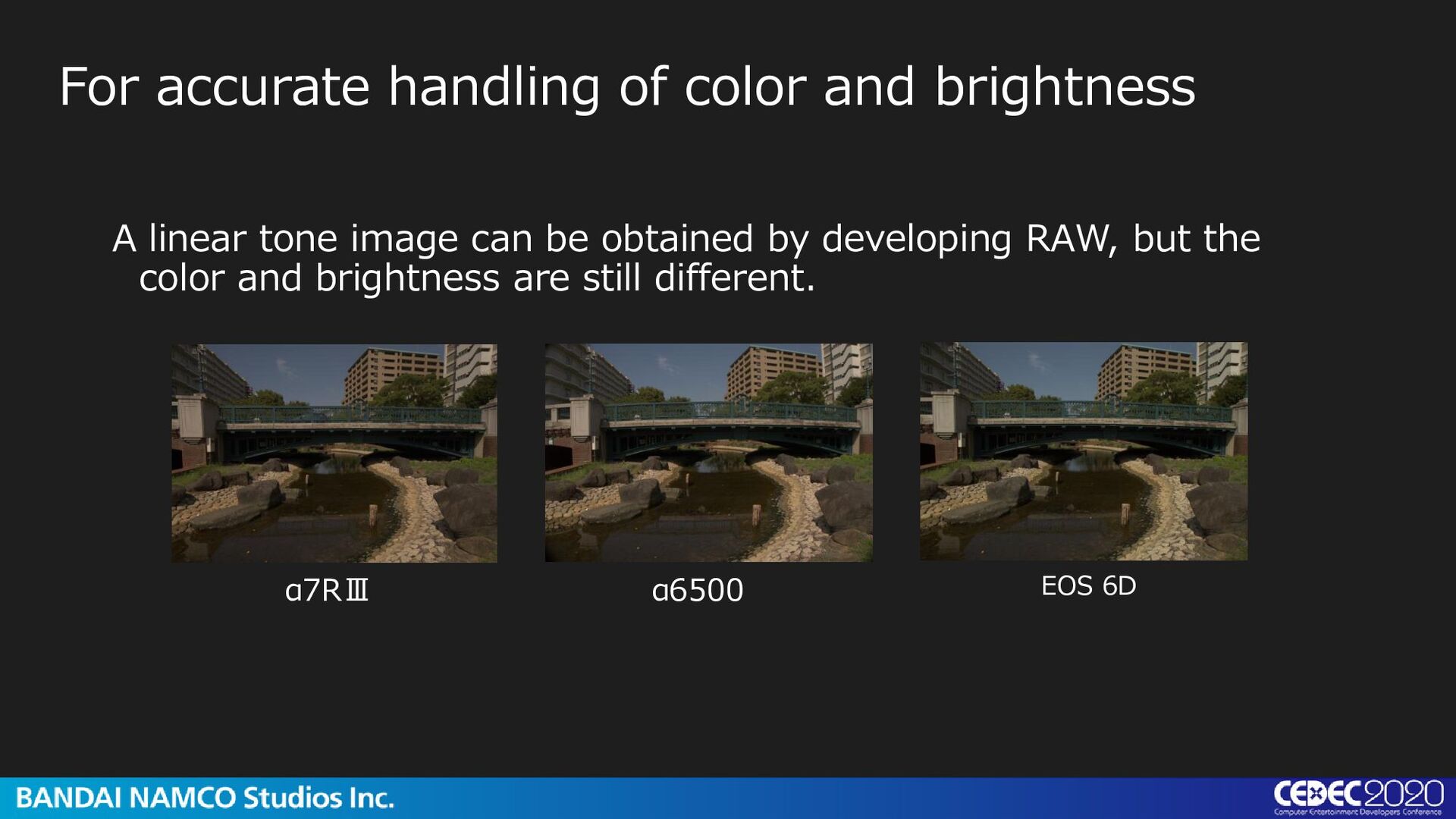
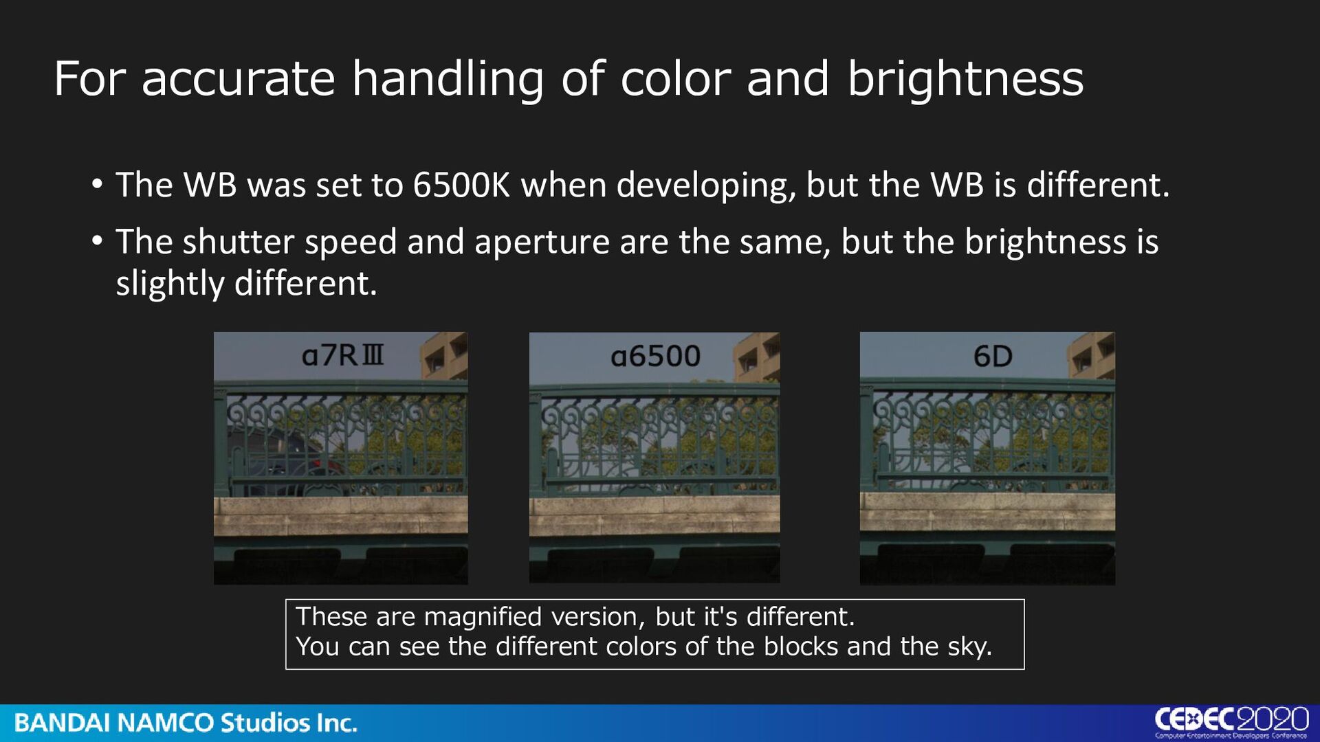
tampered. For accurate handling of color and brightness I set WB to 6500 K in the camera setting, and other than that, I have standard jpeg settings. It has contrast, and each WB is different ... α7RⅢ α6500 EOS 6D Below is a jpeg shot with the same ISO, aperture, and shutter speed.
was set to 6500K when developing, but the WB is different. • The shutter speed and aperture are the same, but the brightness is slightly different. These are magnified version, but it's different. You can see the different colors of the blocks and the sky.
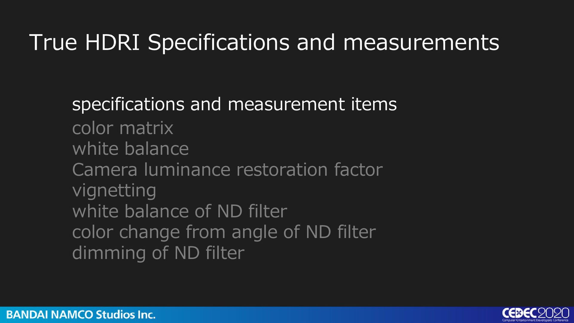
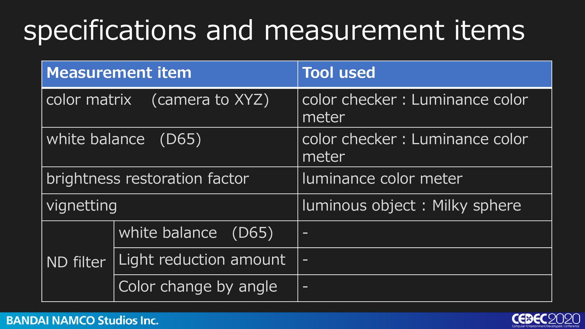
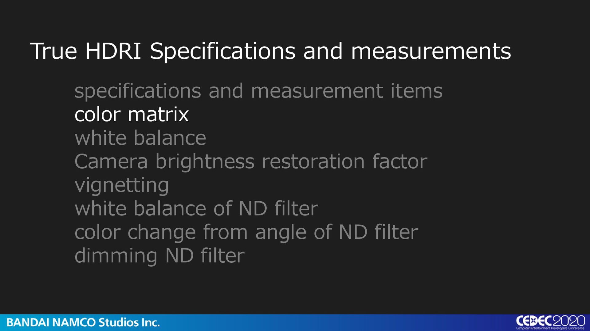
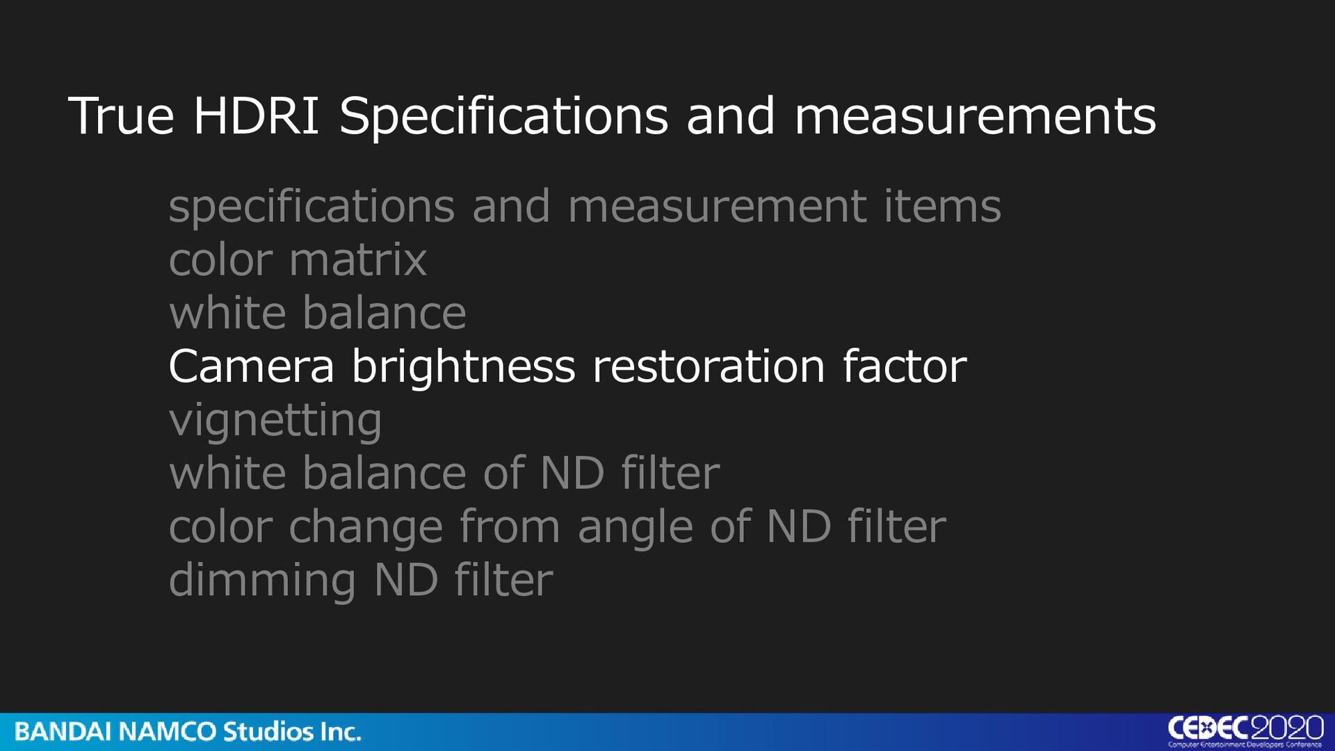
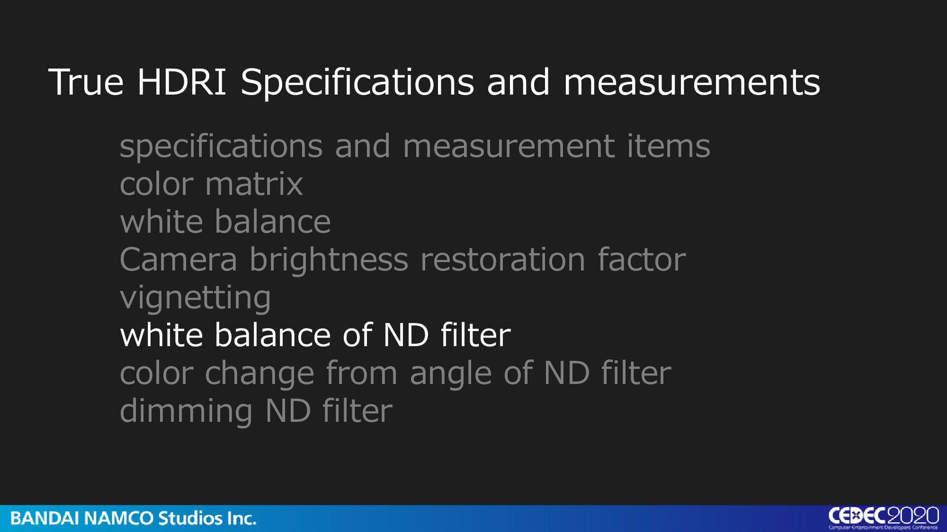
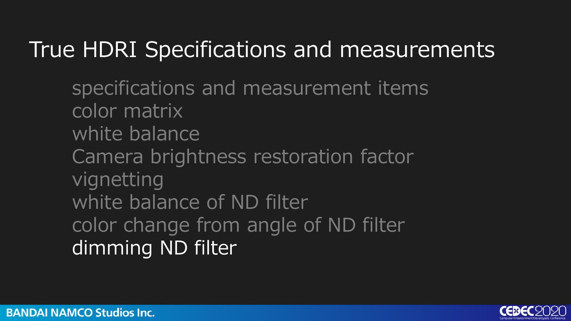
matrix white balance Camera luminance restoration factor vignetting white balance of ND filter color change from angle of ND filter dimming of ND filter
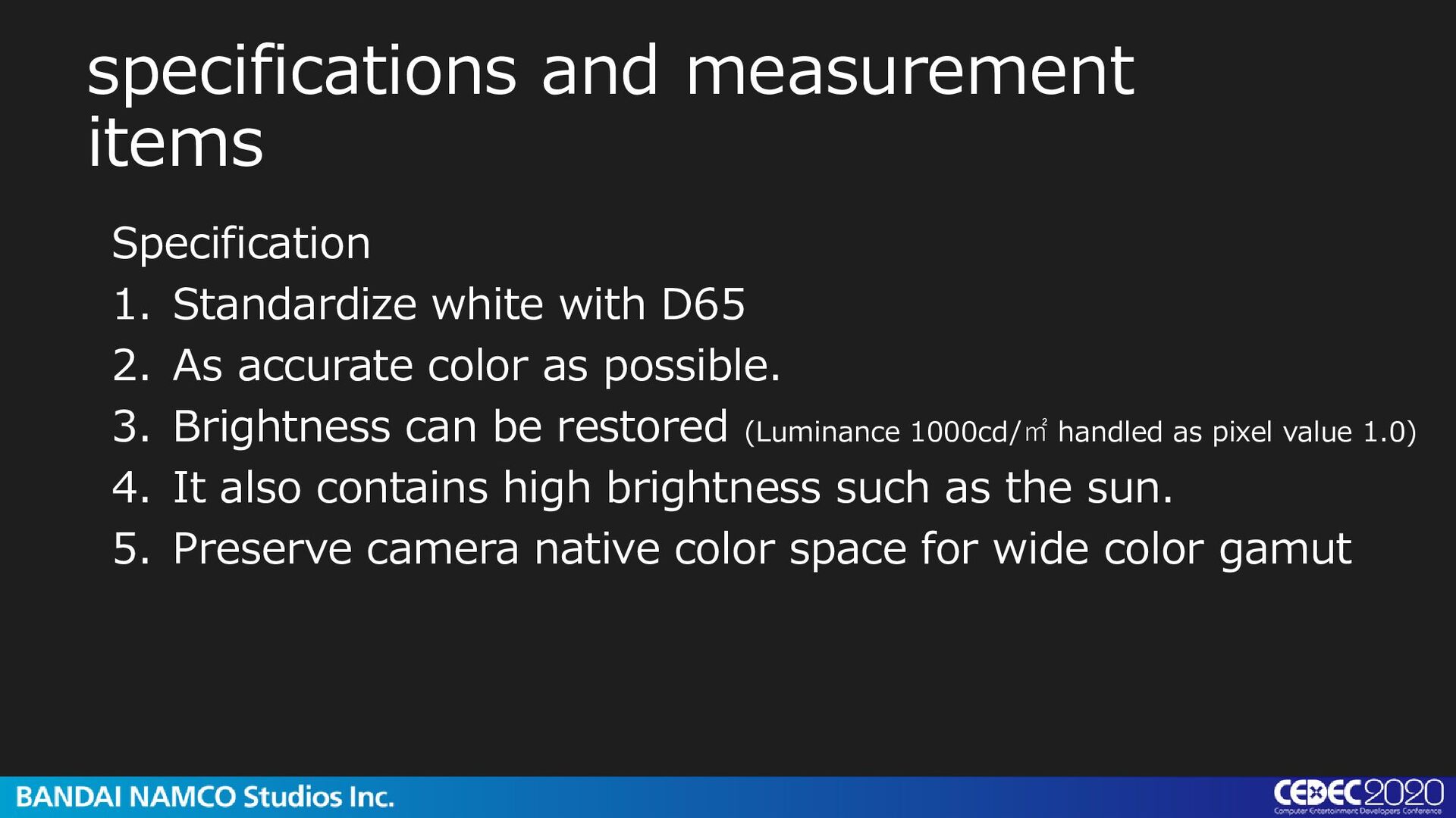
2. As accurate color as possible. 3. Brightness can be restored (Luminance 1000cd/㎡ handled as pixel value 1.0) 4. It also contains high brightness such as the sun. 5. Preserve camera native color space for wide color gamut
(camera to XYZ) color checker:Luminance color meter white balance (D65) color checker:Luminance color meter brightness restoration factor luminance color meter vignetting luminous object : Milky sphere ND filter white balance (D65) - Light reduction amount - Color change by angle -
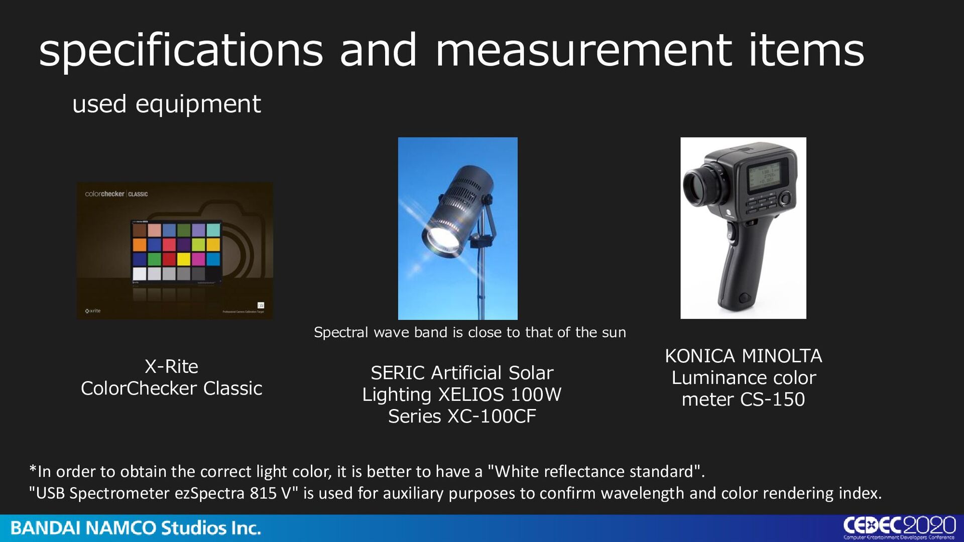
SERIC Artificial Solar Lighting XELIOS 100W Series XC-100CF X-Rite ColorChecker Classic Spectral wave band is close to that of the sun used equipment *In order to obtain the correct light color, it is better to have a "White reflectance standard". "USB Spectrometer ezSpectra 815 V" is used for auxiliary purposes to confirm wavelength and color rendering index.
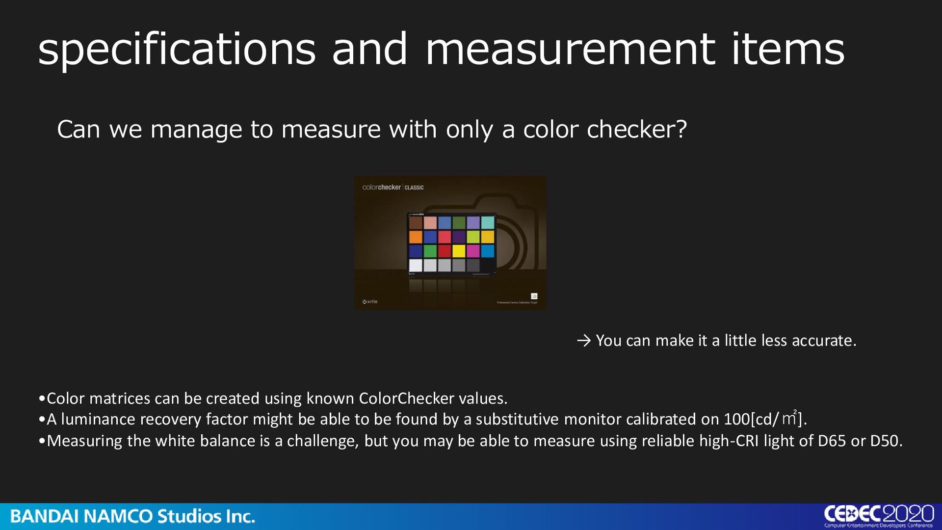
known ColorChecker values. •A luminance recovery factor might be able to be found by a substitutive monitor calibrated on 100[cd/㎡]. •Measuring the white balance is a challenge, but you may be able to measure using reliable high-CRI light of D65 or D50. Can we manage to measure with only a color checker? → You can make it a little less accurate.
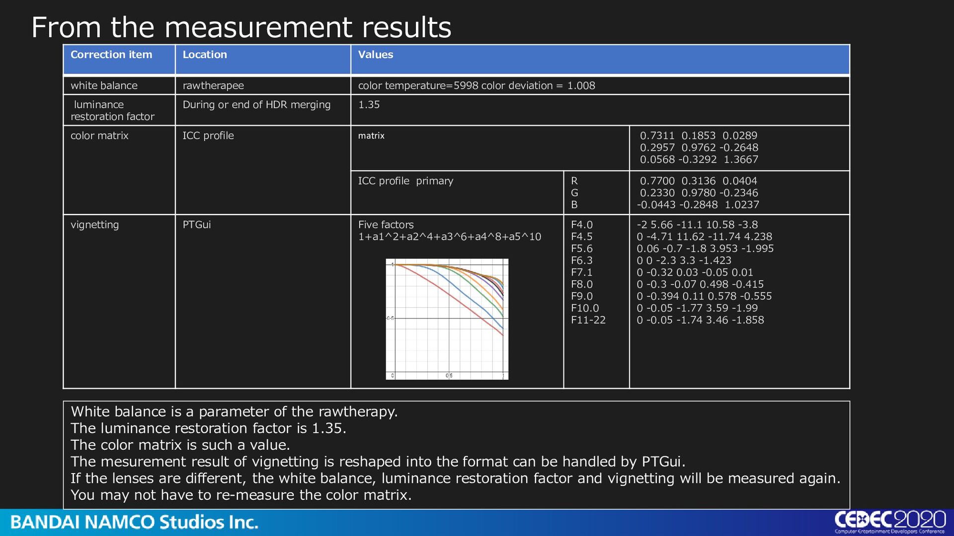
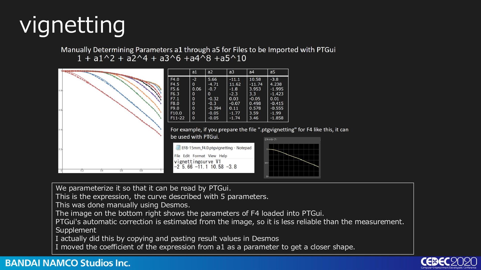
rawtherapee color temperature=5998 color deviation = 1.008 luminance restoration factor During or end of HDR merging 1.35 color matrix ICC profile matrix 0.7311 0.1853 0.0289 0.2957 0.9762 -0.2648 0.0568 -0.3292 1.3667 ICC profile primary R G B 0.7700 0.3136 0.0404 0.2330 0.9780 -0.2346 -0.0443 -0.2848 1.0237 vignetting PTGui Five factors 1+a1^2+a2^4+a3^6+a4^8+a5^10 F4.0 F4.5 F5.6 F6.3 F7.1 F8.0 F9.0 F10.0 F11-22 -2 5.66 -11.1 10.58 -3.8 0 -4.71 11.62 -11.74 4.238 0.06 -0.7 -1.8 3.953 -1.995 0 0 -2.3 3.3 -1.423 0 -0.32 0.03 -0.05 0.01 0 -0.3 -0.07 0.498 -0.415 0 -0.394 0.11 0.578 -0.555 0 -0.05 -1.77 3.59 -1.99 0 -0.05 -1.74 3.46 -1.858 White balance is a parameter of the rawtherapy. The luminance restoration factor is 1.35. The color matrix is such a value. The mesurement result of vignetting is reshaped into the format can be handled by PTGui. If the lenses are different, the white balance, luminance restoration factor and vignetting will be measured again. You may not have to re-measure the color matrix.
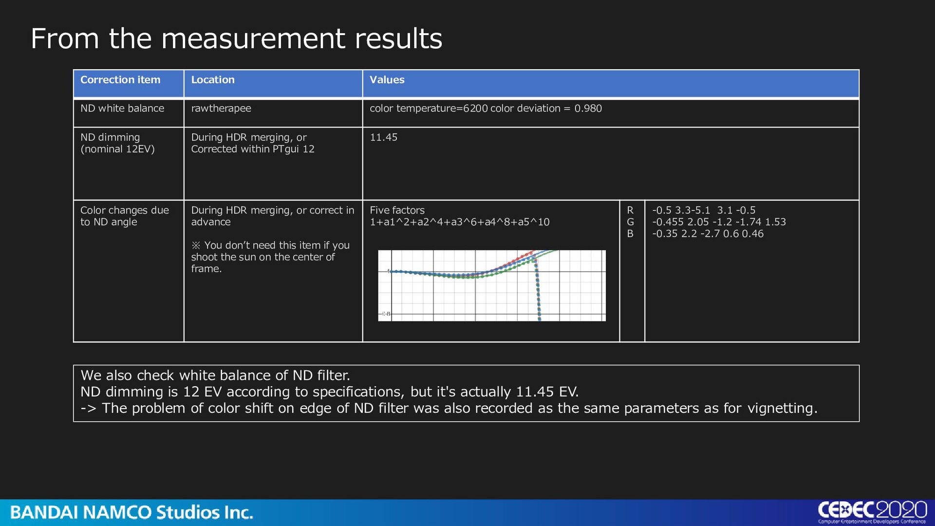
color deviation = 0.980 ND dimming (nominal 12EV) During HDR merging, or Corrected within PTgui 12 11.45 Color changes due to ND angle During HDR merging, or correct in advance ※ You don’t need this item if you shoot the sun on the center of frame. Five factors 1+a1^2+a2^4+a3^6+a4^8+a5^10 R G B -0.5 3.3-5.1 3.1 -0.5 -0.455 2.05 -1.2 -1.74 1.53 -0.35 2.2 -2.7 0.6 0.46 From the measurement results We also check white balance of ND filter. ND dimming is 12 EV according to specifications, but it's actually 11.45 EV. -> The problem of color shift on edge of ND filter was also recorded as the same parameters as for vignetting.
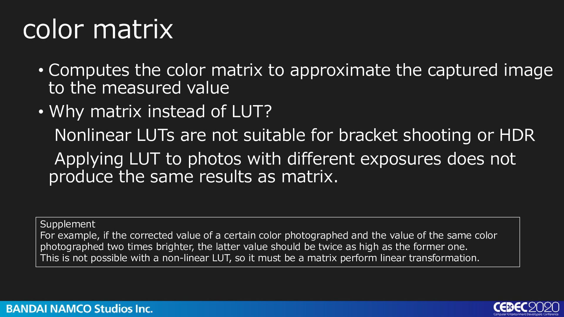
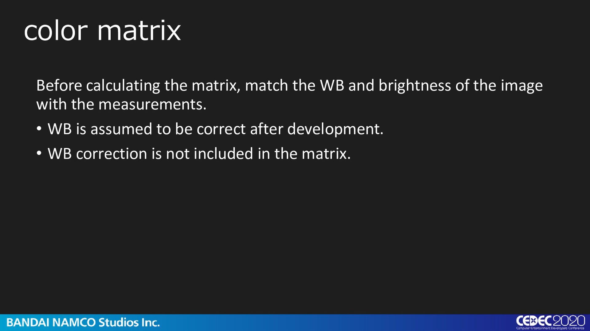
to the measured value • Why matrix instead of LUT? Nonlinear LUTs are not suitable for bracket shooting or HDR Applying LUT to photos with different exposures does not produce the same results as matrix. color matrix Supplement For example, if the corrected value of a certain color photographed and the value of the same color photographed two times brighter, the latter value should be twice as high as the former one. This is not possible with a non-linear LUT, so it must be a matrix perform linear transformation.
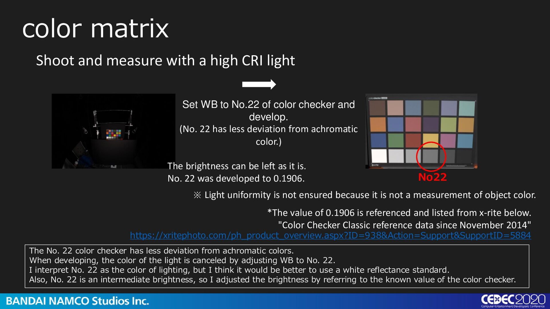
*The value of 0.1906 is referenced and listed from x-rite below. "Color Checker Classic reference data since November 2014" https://xritephoto.com/ph_product_overview.aspx?ID=938&Action=Support&SupportID=5884 ※ Light uniformity is not ensured because it is not a measurement of object color. Set WB to No.22 of color checker and develop. (No. 22 has less deviation from achromatic color.) The brightness can be left as it is. No. 22 was developed to 0.1906. No22 The No. 22 color checker has less deviation from achromatic colors. When developing, the color of the light is canceled by adjusting WB to No. 22. I interpret No. 22 as the color of lighting, but I think it would be better to use a white reflectance standard. Also, No. 22 is an intermediate brightness, so I adjusted the brightness by referring to the known value of the color checker.
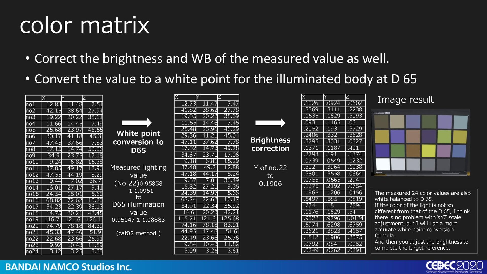
42.15 38.64 27.94 no3 19.22 20.22 38.61 no4 11.66 14.45 7.49 no5 25.68 23.97 46.55 no6 30.17 41.18 45.3 no7 47.45 37.66 7.83 no8 17.15 14.74 50.06 no9 34.9 23.75 17.16 no10 9.24 6.82 15.38 no11 37.85 49.17 12.96 no12 47.55 44.19 8.29 no13 9.44 7.02 36.7 no14 16.01 27.17 9.41 no15 24.54 15.01 5.69 no16 68.82 72.62 10.23 no17 34.23 22.39 36.13 no18 14.75 20.21 42.45 no19 116.7 121.6 126.4 no20 74.79 78.18 84.39 no21 45.33 47.46 51.9 no22 22.68 23.66 25.91 no23 9.92 10.43 11.89 no24 3.12 3.25 3.63 X Y Z .1026 .0924 .0602 .3369 .3111 .2238 .1535 .1629 .3093 .093 .1165 .06 .2052 .193 .3729 .2406 .332 .3628 .3795 .3031 .0627 .1371 .1187 .401 .2793 .191 .1374 .0739 .0549 .1232 .302 .3964 .1038 .3801 .3558 .0664 .0755 .0565 .294 .1275 .2192 .0754 .1965 .1206 .0456 .5497 .585 .0819 .274 .18 .2894 .1176 .1629 .34 .9322 .9796 1.0124 .5974 .6298 .6759 .3621 .3823 .4157 .1812 .1906 .2075 .0792 .084 .0952 .0249 .0262 .0291 X Y Z 12.73 11.47 7.47 41.82 38.62 27.78 19.05 20.22 38.39 11.55 14.46 7.45 25.48 23.96 46.29 29.86 41.21 45.04 47.11 37.62 7.78 17.02 14.73 49.78 34.67 23.71 17.06 9.18 6.81 15.29 37.48 49.2 12.88 47.18 44.17 8.24 9.37 7.01 36.49 15.82 27.21 9.35 24.39 14.97 5.66 68.24 72.62 10.17 34.01 22.34 35.92 14.6 20.23 42.21 115.71 121.6 125.68 74.16 78.18 83.91 44.95 47.46 51.6 22.49 23.66 25.76 9.84 10.43 11.82 3.09 3.25 3.61 White point conversion to D65 Measured lighting value (No.22)0.95858 1 1.0951 to D65 illumination value 0.95047 1 1.08883 (cat02 method ) Brightness correction Y of no.22 to 0.1906 • Correct the brightness and WB of the measured value as well. • Convert the value to a white point for the illuminated body at D 65 Image result The measured 24 color values are also white balanced to D 65. If the color of the light is not so different from that of the D 65, I think there is no problem with XYZ scale adjustment, but I will use a more accurate white point conversion formula. And then you adjust the brightness to complete the target reference.
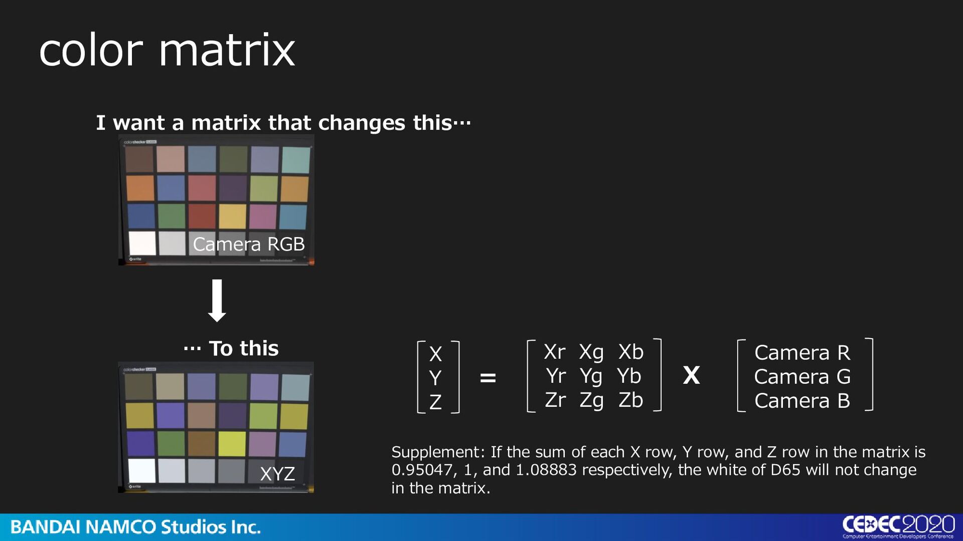
To this X Y Z Camera R Camera G Camera B Xr Xg Xb Yr Yg Yb Zr Zg Zb = X Camera RGB XYZ Supplement: If the sum of each X row, Y row, and Z row in the matrix is 0.95047, 1, and 1.08883 respectively, the white of D65 will not change in the matrix.
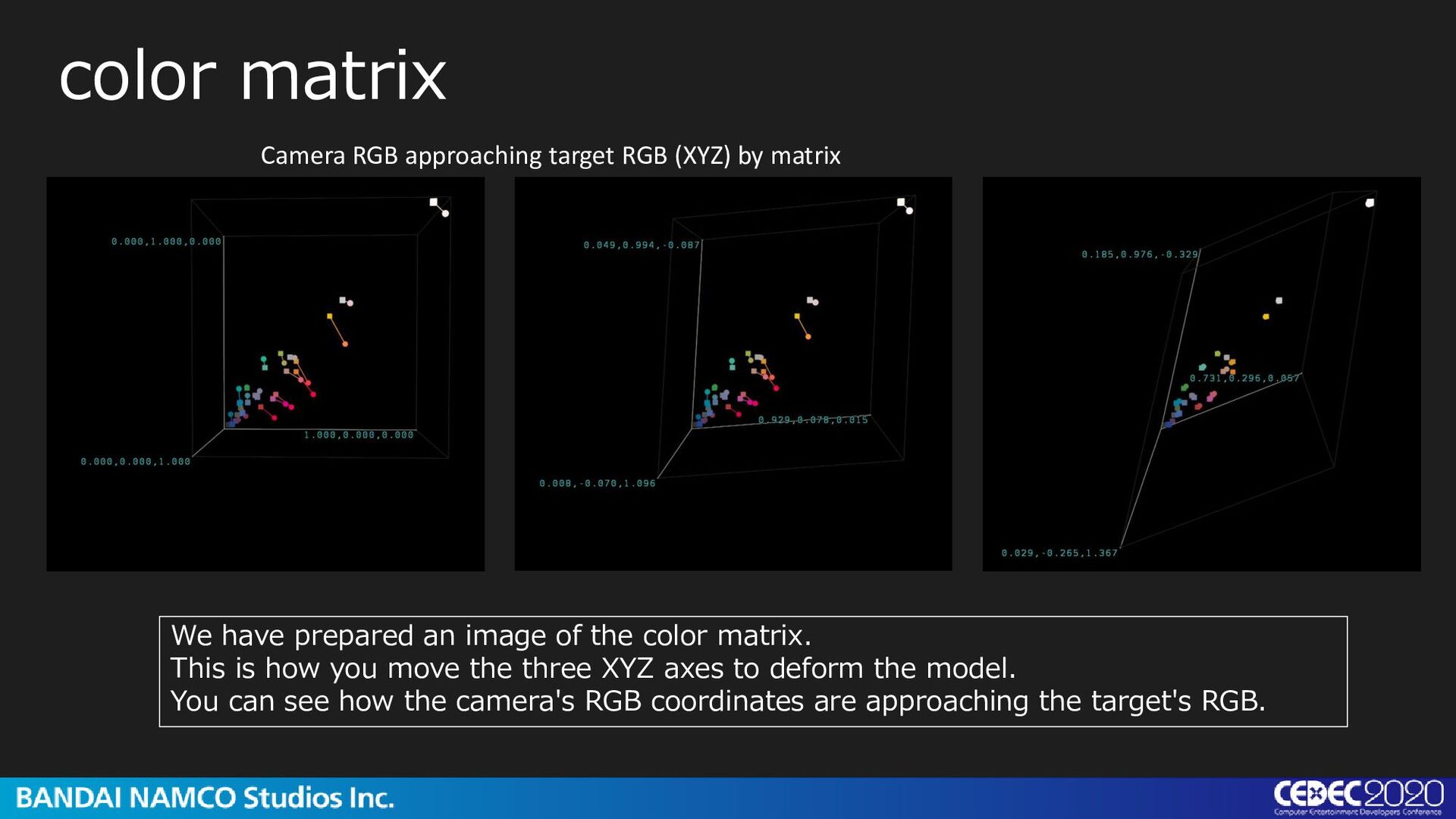
We have prepared an image of the color matrix. This is how you move the three XYZ axes to deform the model. You can see how the camera's RGB coordinates are approaching the target's RGB.
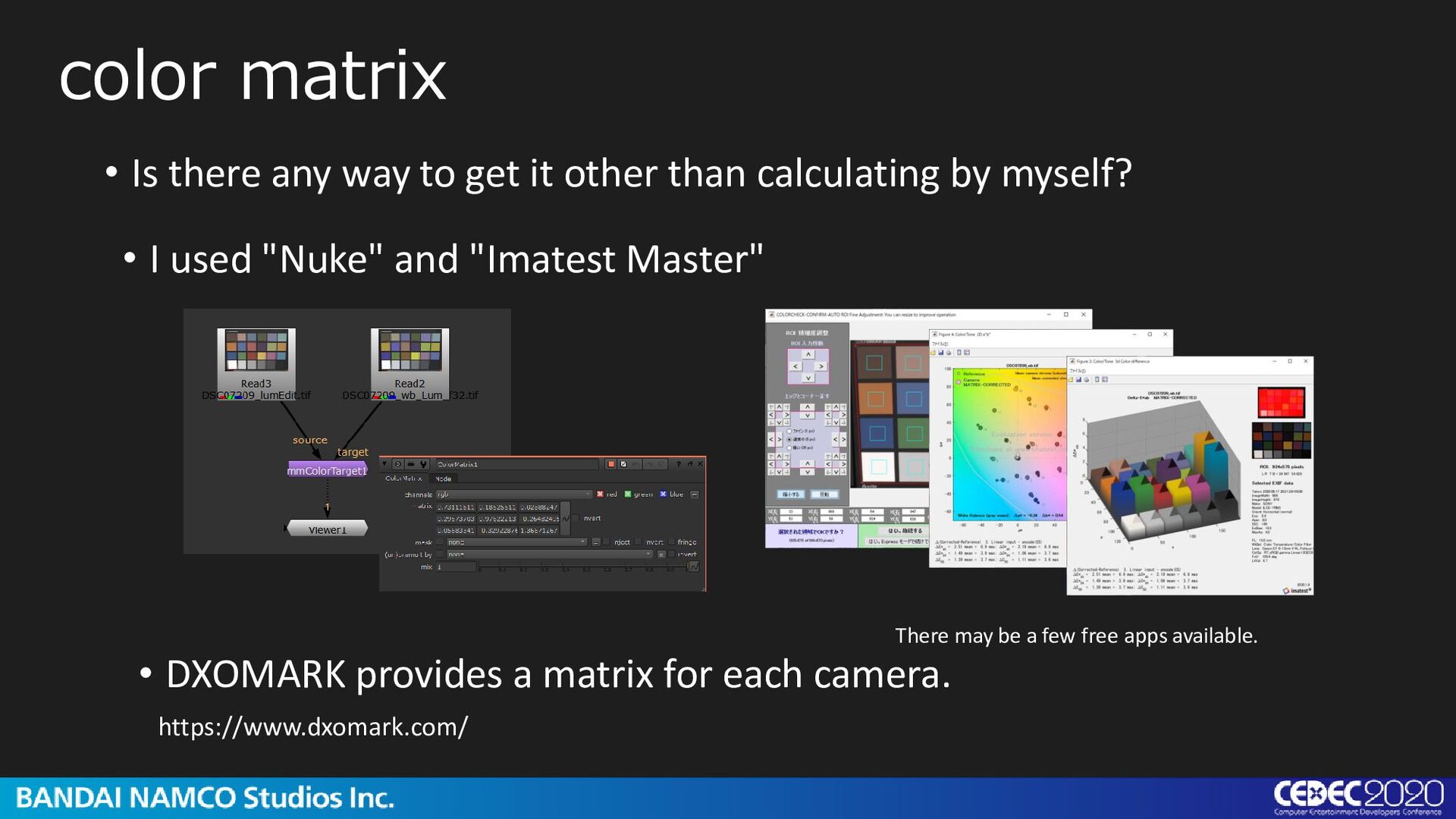
Is there any way to get it other than calculating by myself? • DXOMARK provides a matrix for each camera. There may be a few free apps available. https://www.dxomark.com/
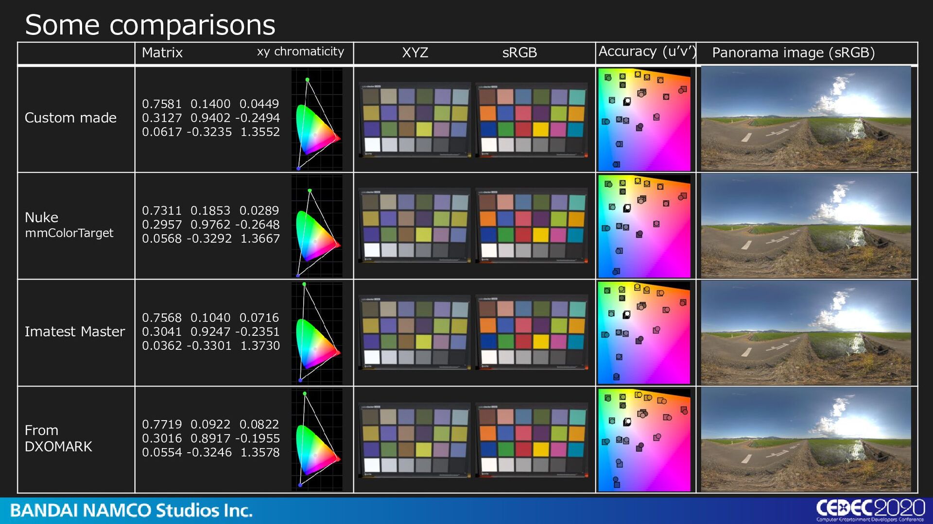
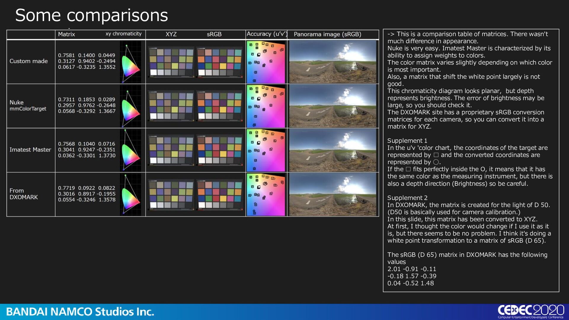
There wasn't much difference in appearance. Nuke is very easy. Imatest Master is characterized by its ability to assign weights to colors. The color matrix varies slightly depending on which color is most important. Also, a matrix that shift the white point largely is not good. This chromaticity diagram looks planar, but depth represents brightness. The error of brightness may be large, so you should check it. The DXOMARK site has a proprietary sRGB conversion matrices for each camera, so you can convert it into a matrix for XYZ. Supplement 1 In the u'v 'color chart, the coordinates of the target are represented by □ and the converted coordinates are represented by ◯. If the □ fits perfectly inside the O, it means that it has the same color as the measuring instrument, but there is also a depth direction (Brightness) so be careful. Supplement 2 In DXOMARK, the matrix is created for the light of D 50. (D50 is basically used for camera calibration.) In this slide, this matrix has been converted to XYZ. At first, I thought the color would change if I use it as it is, but there seems to be no problem. I think it's doing a white point transformation to a matrix of sRGB (D 65). The sRGB (D 65) matrix in DXOMARK has the following values 2.01 -0.91 -0.11 -0.18 1.57 -0.39 0.04 -0.52 1.48
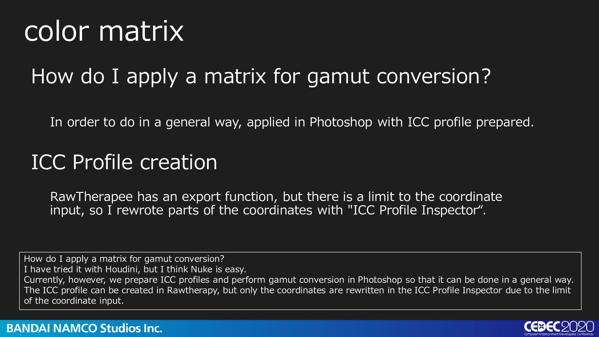
conversion? In order to do in a general way, applied in Photoshop with ICC profile prepared. How do I apply a matrix for gamut conversion? I have tried it with Houdini, but I think Nuke is easy. Currently, however, we prepare ICC profiles and perform gamut conversion in Photoshop so that it can be done in a general way. The ICC profile can be created in Rawtherapy, but only the coordinates are rewritten in the ICC Profile Inspector due to the limit of the coordinate input. RawTherapee has an export function, but there is a limit to the coordinate input, so I rewrote parts of the coordinates with "ICC Profile Inspector“. ICC Profile creation
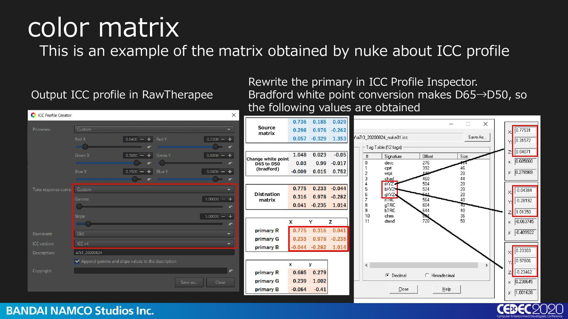
by nuke about ICC profile Output ICC profile in RawTherapee Rewrite the primary in ICC Profile Inspector. Bradford white point conversion makes D65→D50, so the following values are obtained Distnation matrix Change white point D65 to D50 (bradford) Source matrix
profile. Set the indicated values in RawTherapee like this, and rewrite the coordinates in the ICC Profile Inspector after exporting. In ICC Profile Inspector, the specification is to write a value converted to D50, so rewrite it to such values.
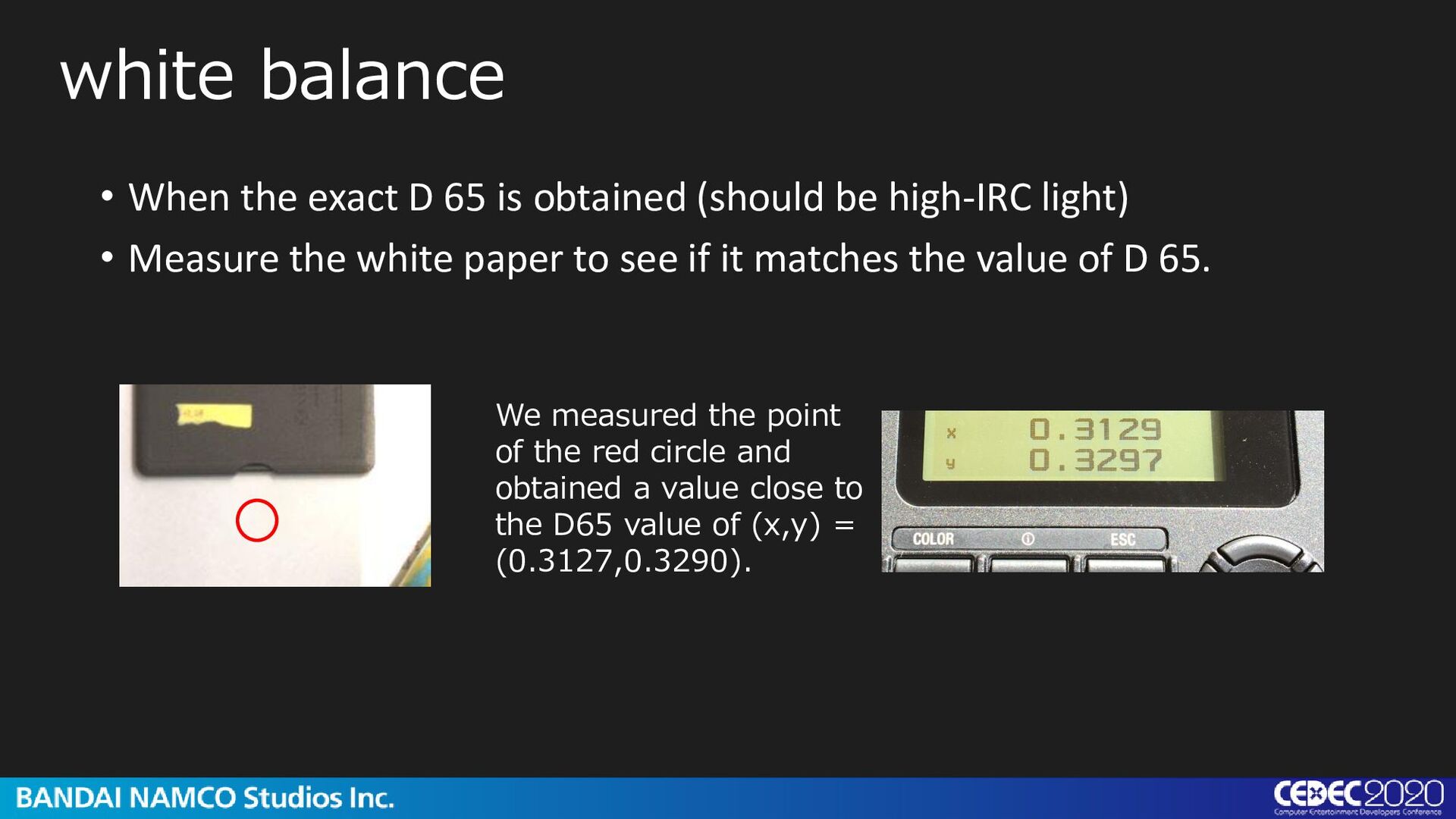
high-IRC light) • Measure the white paper to see if it matches the value of D 65. white balance We measured the point of the red circle and obtained a value close to the D65 value of (x,y) = (0.3127,0.3290).
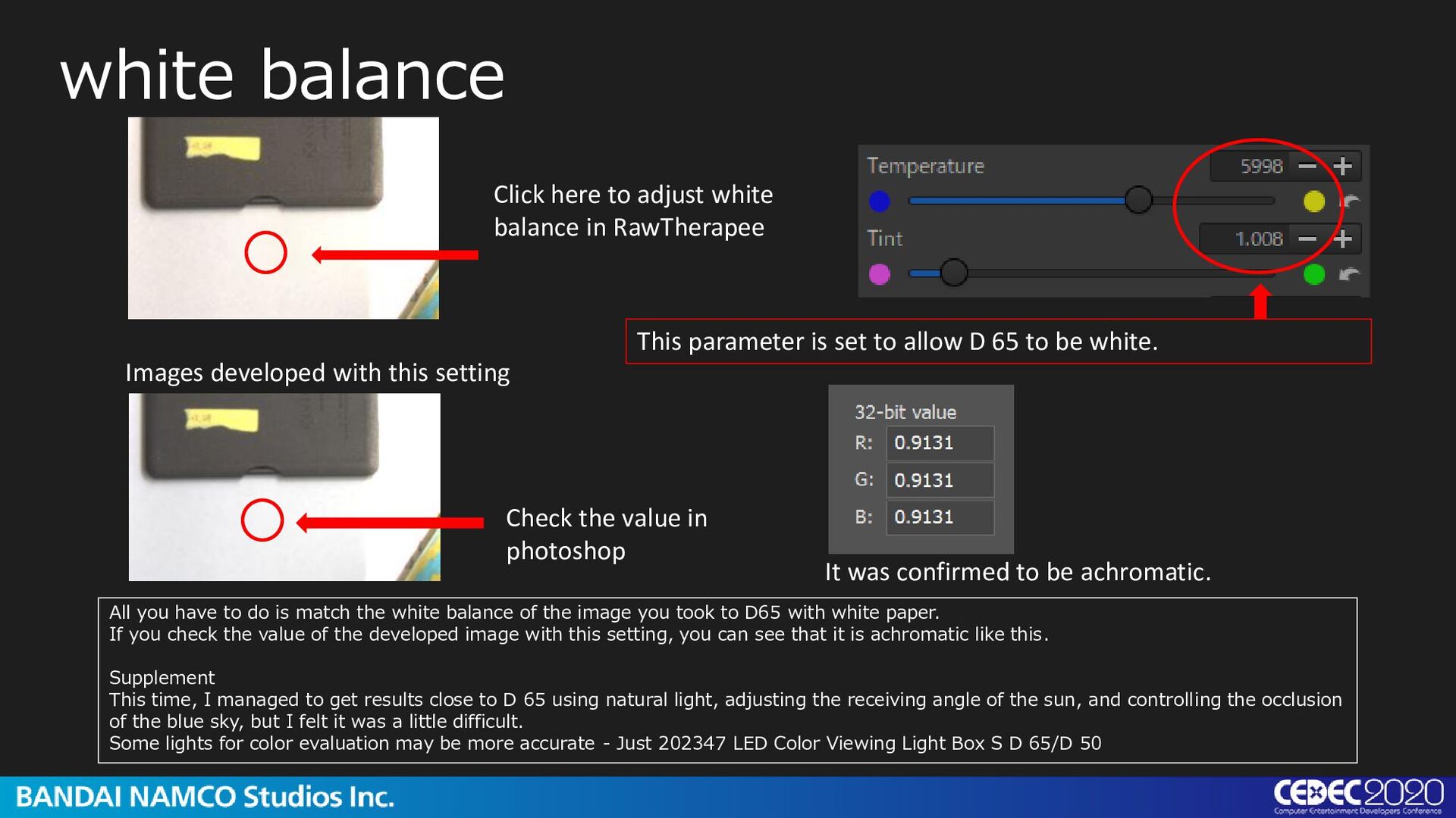
This parameter is set to allow D 65 to be white. Images developed with this setting Check the value in photoshop It was confirmed to be achromatic. All you have to do is match the white balance of the image you took to D65 with white paper. If you check the value of the developed image with this setting, you can see that it is achromatic like this. Supplement This time, I managed to get results close to D 65 using natural light, adjusting the receiving angle of the sun, and controlling the occlusion of the blue sky, but I felt it was a little difficult. Some lights for color evaluation may be more accurate - Just 202347 LED Color Viewing Light Box S D 65/D 50
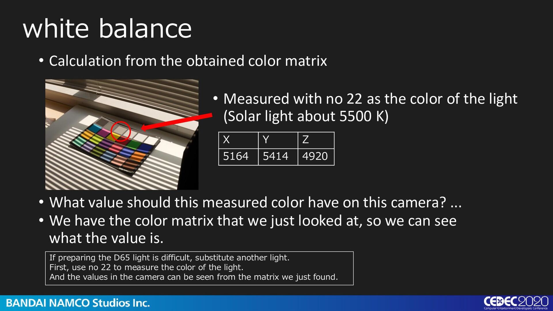
Measured with no 22 as the color of the light (Solar light about 5500 K) X Y Z 5164 5414 4920 • What value should this measured color have on this camera? ... • We have the color matrix that we just looked at, so we can see what the value is. If preparing the D65 light is difficult, substitute another light. First, use no 22 to measure the color of the light. And the values in the camera can be seen from the matrix we just found.
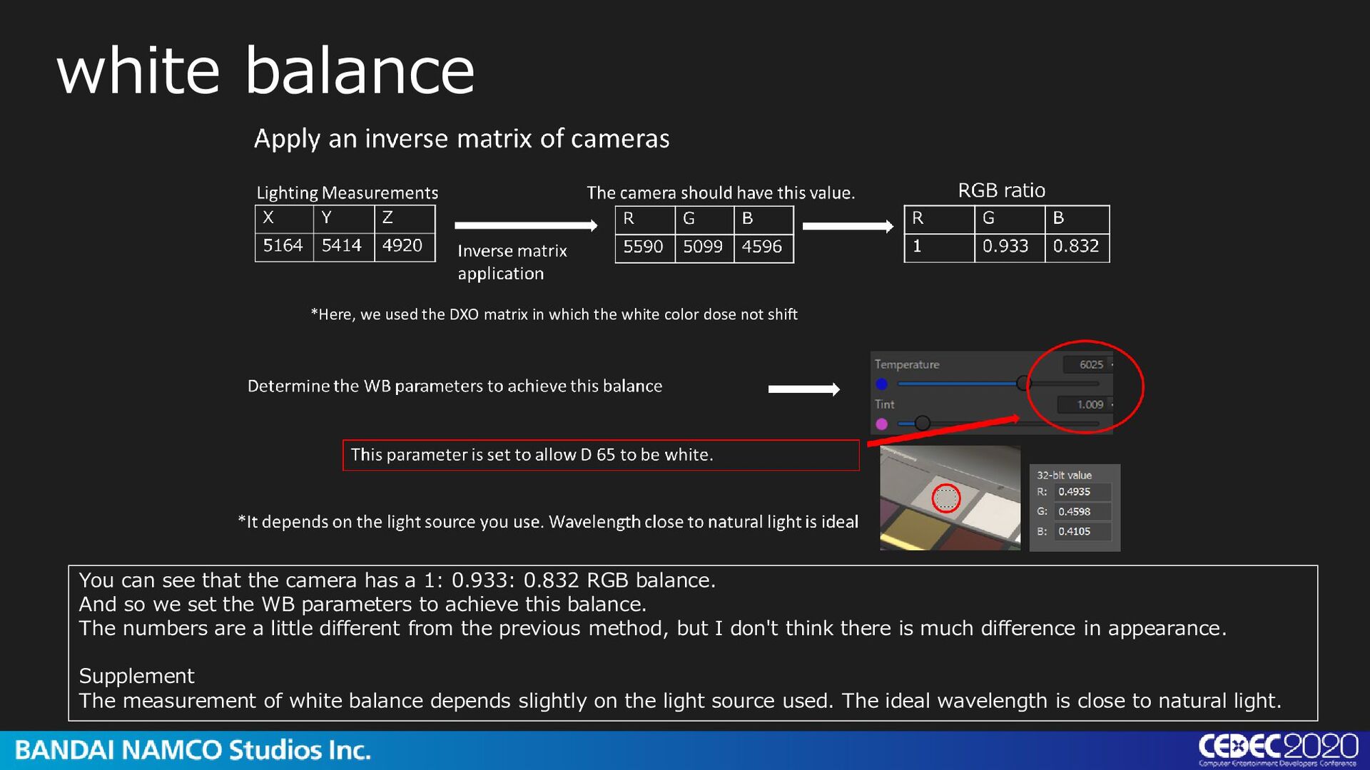
1: 0.933: 0.832 RGB balance. And so we set the WB parameters to achieve this balance. The numbers are a little different from the previous method, but I don't think there is much difference in appearance. Supplement The measurement of white balance depends slightly on the light source used. The ideal wavelength is close to natural light. *Here, we used the DXO matrix in which the white color dose not shift
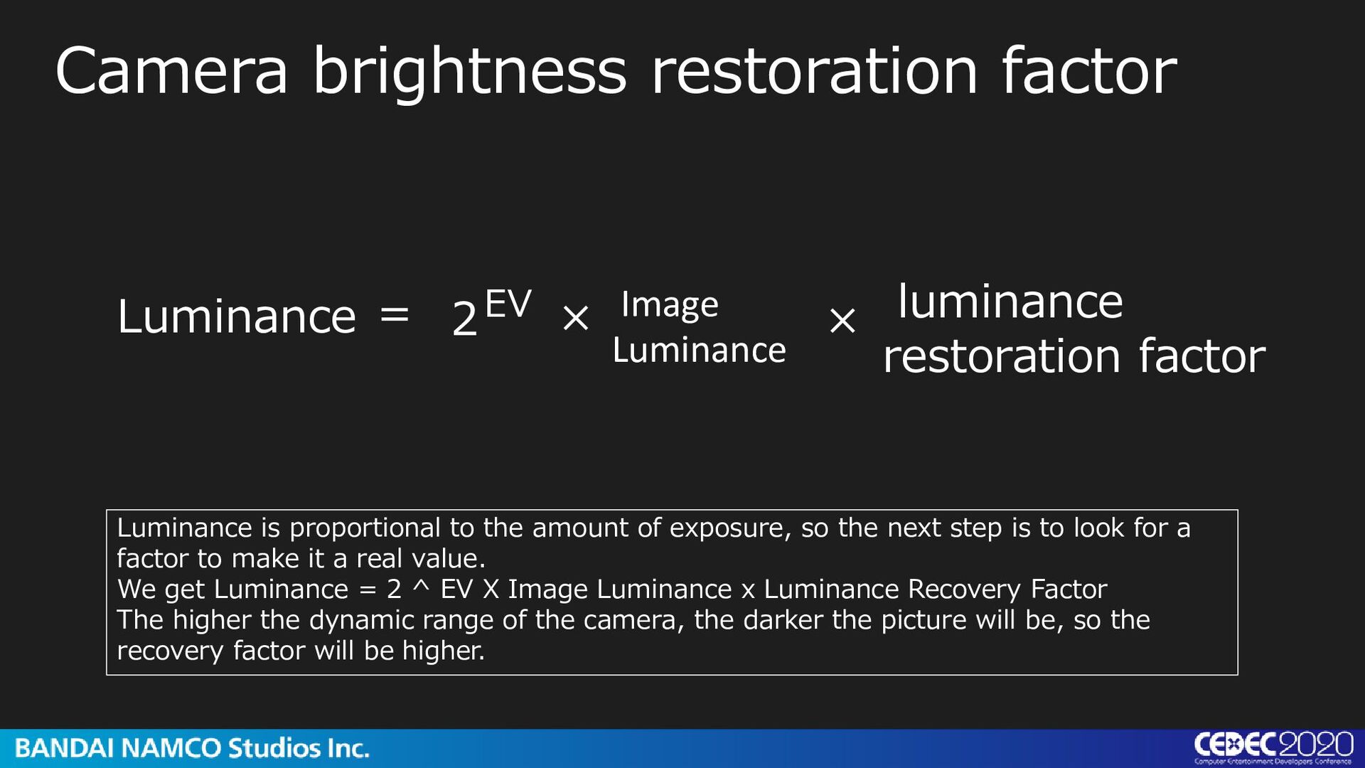
restoration factor Luminance = Luminance is proportional to the amount of exposure, so the next step is to look for a factor to make it a real value. We get Luminance = 2 ^ EV X Image Luminance x Luminance Recovery Factor The higher the dynamic range of the camera, the darker the picture will be, so the recovery factor will be higher.
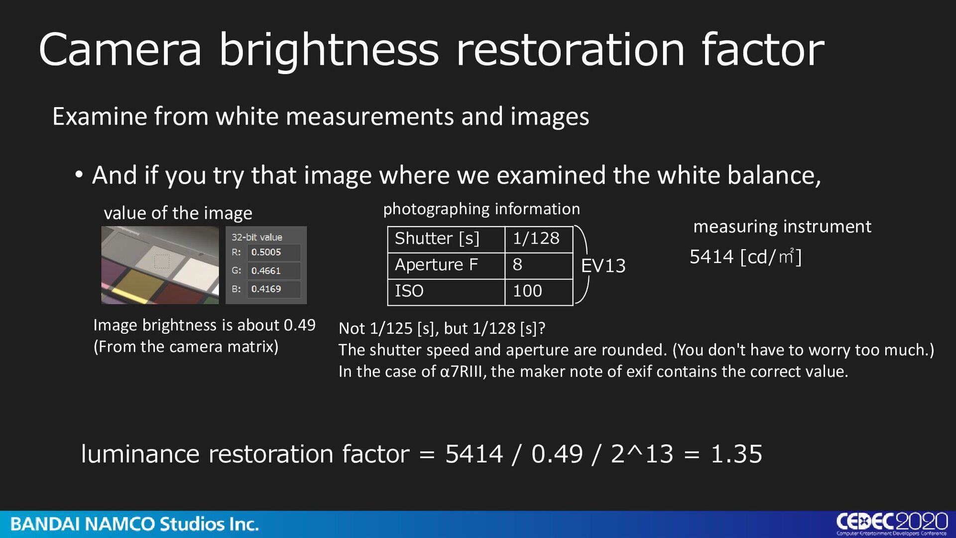
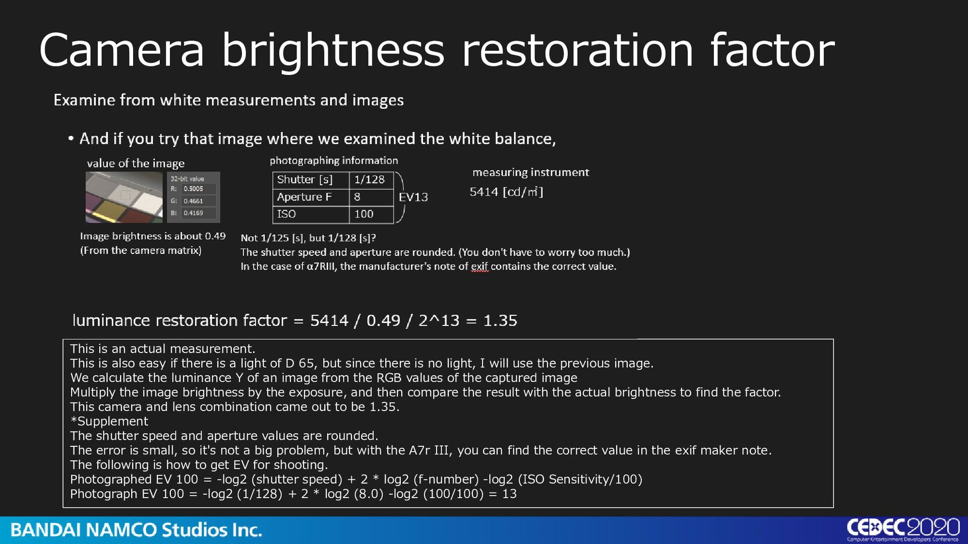
image where we examined the white balance, Examine from white measurements and images value of the image photographing information Shutter [s] 1/128 Aperture F 8 ISO 100 Image brightness is about 0.49 (From the camera matrix) EV13 measuring instrument 5414 [cd/㎡] luminance restoration factor = 5414 / 0.49 / 2^13 = 1.35 Not 1/125 [s], but 1/128 [s]? The shutter speed and aperture are rounded. (You don't have to worry too much.) In the case of α7RIII, the maker note of exif contains the correct value.
is also easy if there is a light of D 65, but since there is no light, I will use the previous image. We calculate the luminance Y of an image from the RGB values of the captured image Multiply the image brightness by the exposure, and then compare the result with the actual brightness to find the factor. This camera and lens combination came out to be 1.35. *Supplement The shutter speed and aperture values are rounded. The error is small, so it's not a big problem, but with the A7r III, you can find the correct value in the exif maker note. The following is how to get EV for shooting. Photographed EV 100 = -log2 (shutter speed) + 2 * log2 (f-number) -log2 (ISO Sensitivity/100) Photograph EV 100 = -log2 (1/128) + 2 * log2 (8.0) -log2 (100/100) = 13
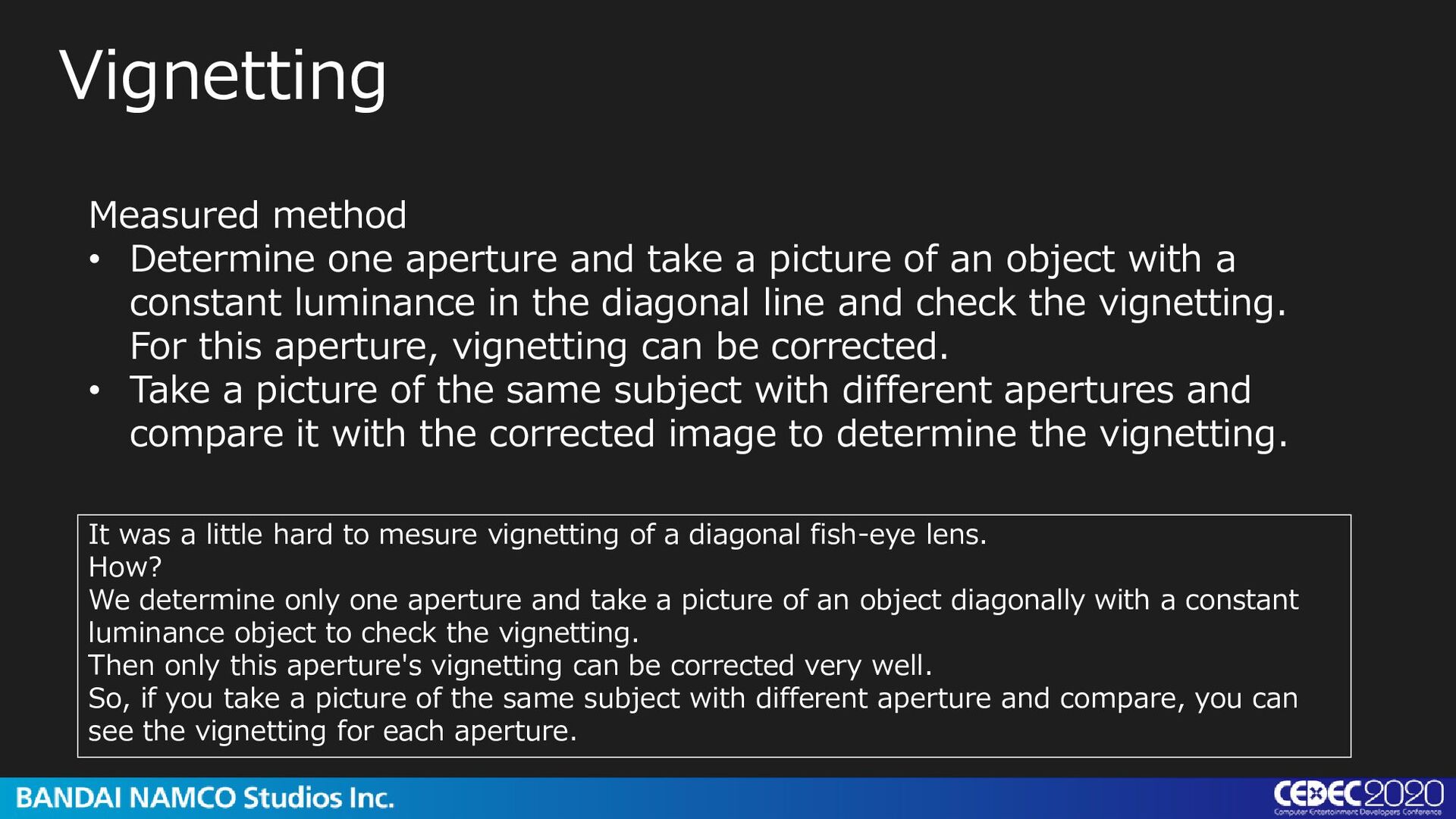
of an object with a constant luminance in the diagonal line and check the vignetting. For this aperture, vignetting can be corrected. • Take a picture of the same subject with different apertures and compare it with the corrected image to determine the vignetting. Vignetting It was a little hard to mesure vignetting of a diagonal fish-eye lens. How? We determine only one aperture and take a picture of an object diagonally with a constant luminance object to check the vignetting. Then only this aperture's vignetting can be corrected very well. So, if you take a picture of the same subject with different aperture and compare, you can see the vignetting for each aperture.
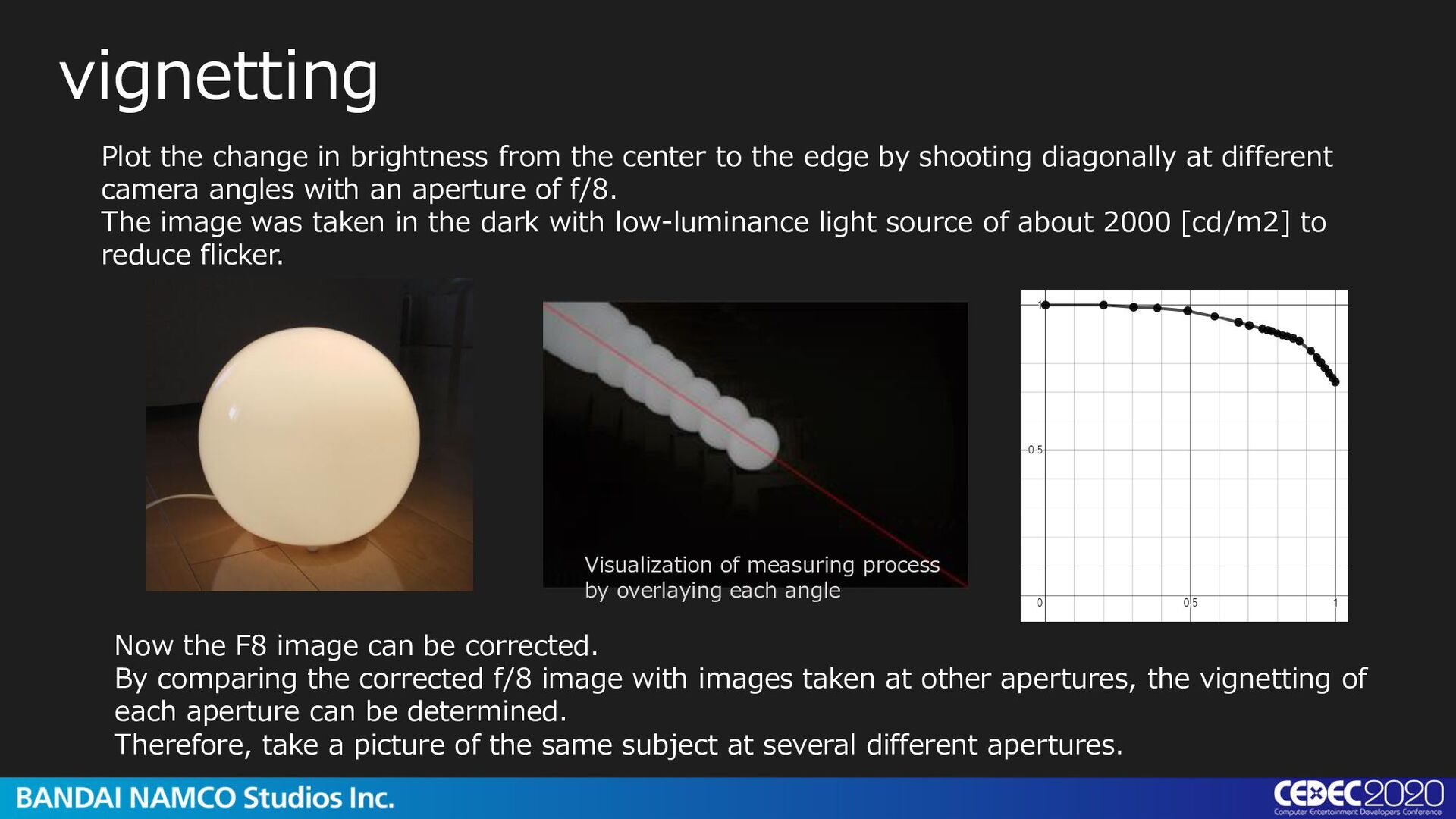
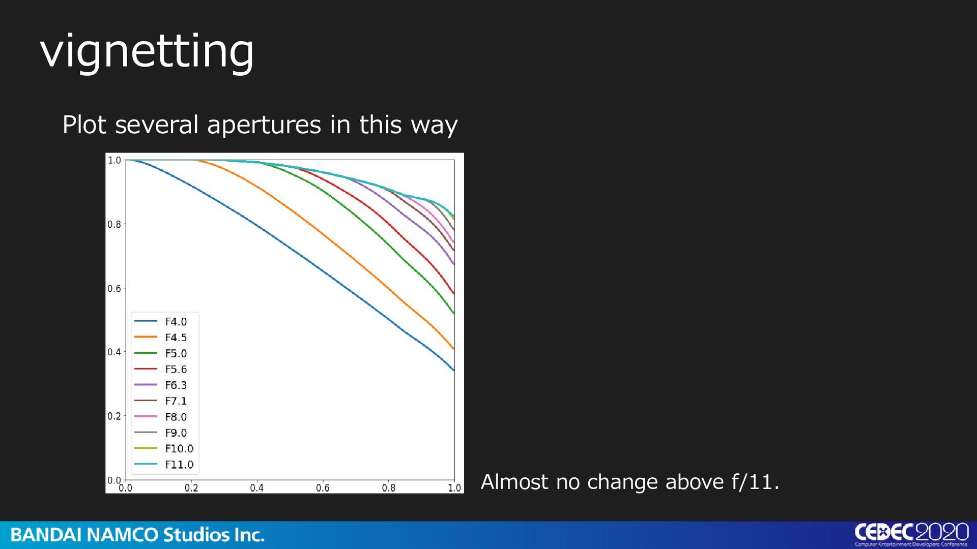
corrected f/8 image with images taken at other apertures, the vignetting of each aperture can be determined. Therefore, take a picture of the same subject at several different apertures. vignetting Plot the change in brightness from the center to the edge by shooting diagonally at different camera angles with an aperture of f/8. The image was taken in the dark with low-luminance light source of about 2000 [cd/m2] to reduce flicker. Visualization of measuring process by overlaying each angle
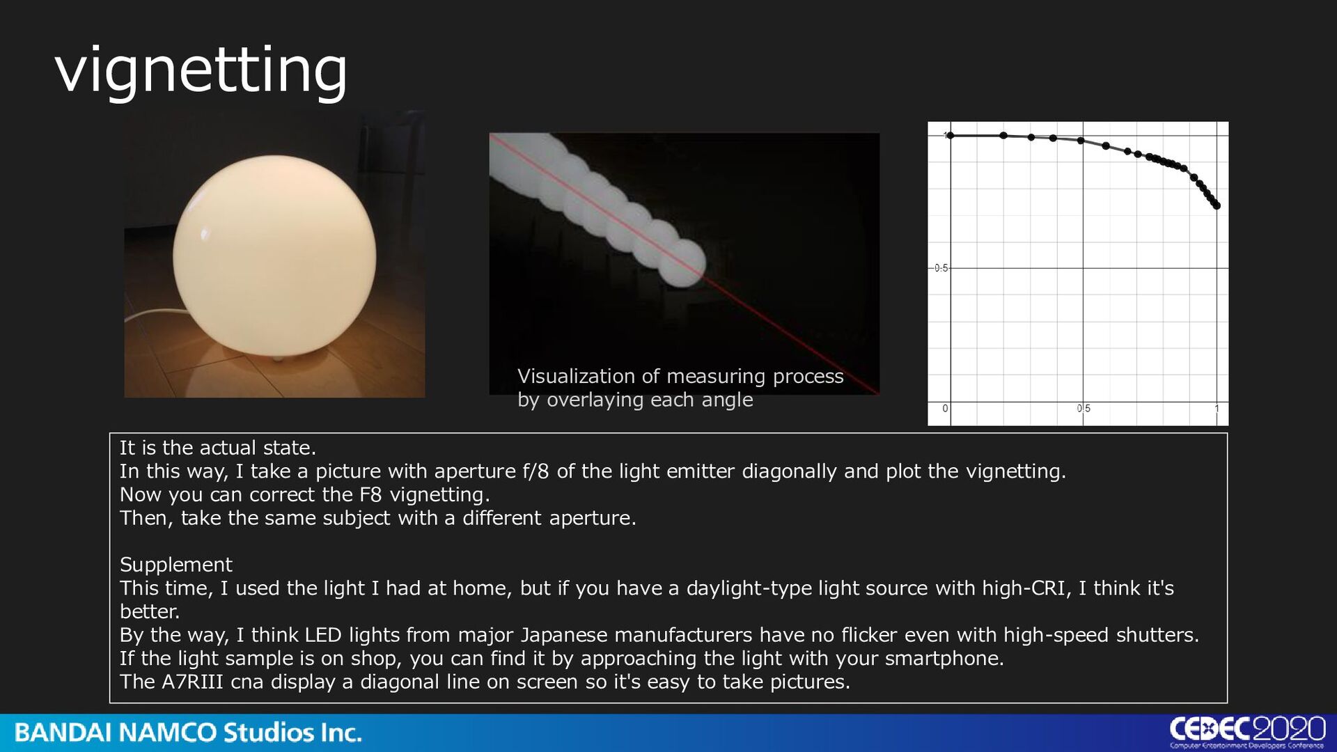
take a picture with aperture f/8 of the light emitter diagonally and plot the vignetting. Now you can correct the F8 vignetting. Then, take the same subject with a different aperture. Supplement This time, I used the light I had at home, but if you have a daylight-type light source with high-CRI, I think it's better. By the way, I think LED lights from major Japanese manufacturers have no flicker even with high-speed shutters. If the light sample is on shop, you can find it by approaching the light with your smartphone. The A7RIII cna display a diagonal line on screen so it's easy to take pictures. Visualization of measuring process by overlaying each angle
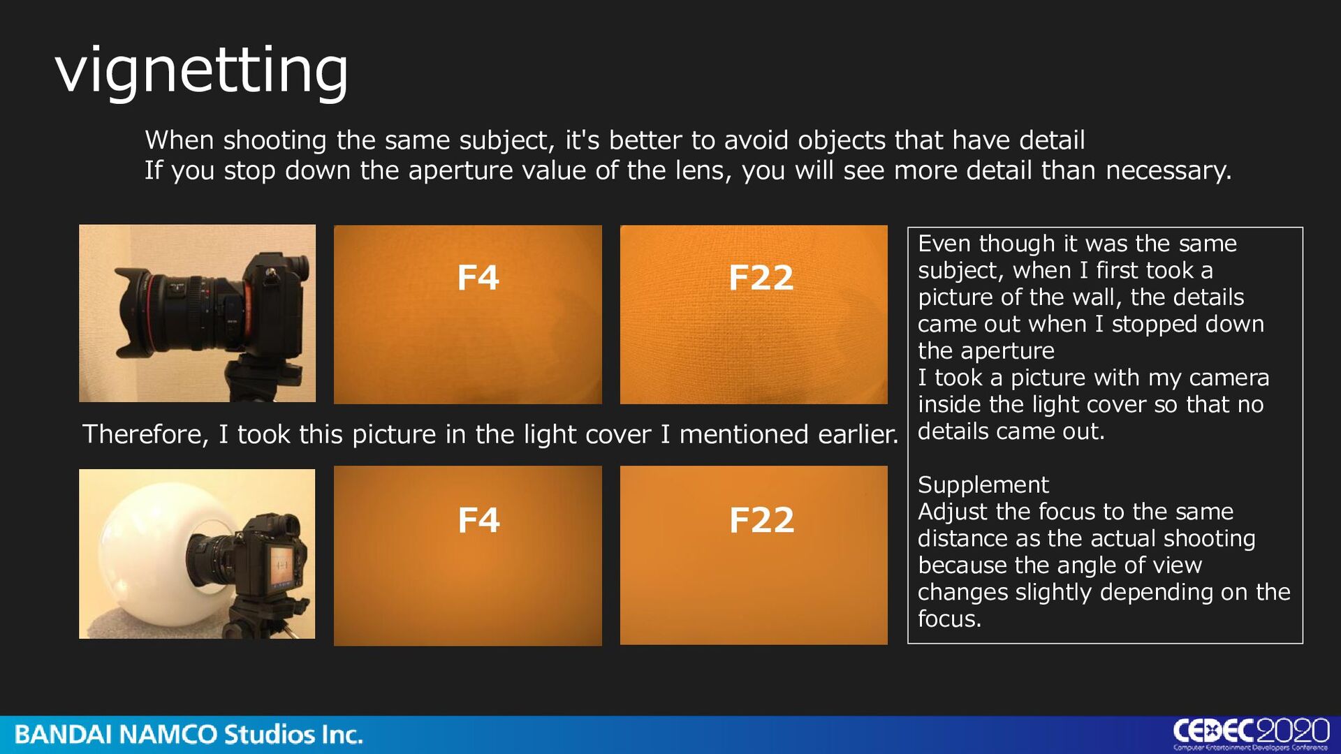
that have detail If you stop down the aperture value of the lens, you will see more detail than necessary. vignetting F4 F22 F4 F22 Therefore, I took this picture in the light cover I mentioned earlier. Even though it was the same subject, when I first took a picture of the wall, the details came out when I stopped down the aperture I took a picture with my camera inside the light cover so that no details came out. Supplement Adjust the focus to the same distance as the actual shooting because the angle of view changes slightly depending on the focus.
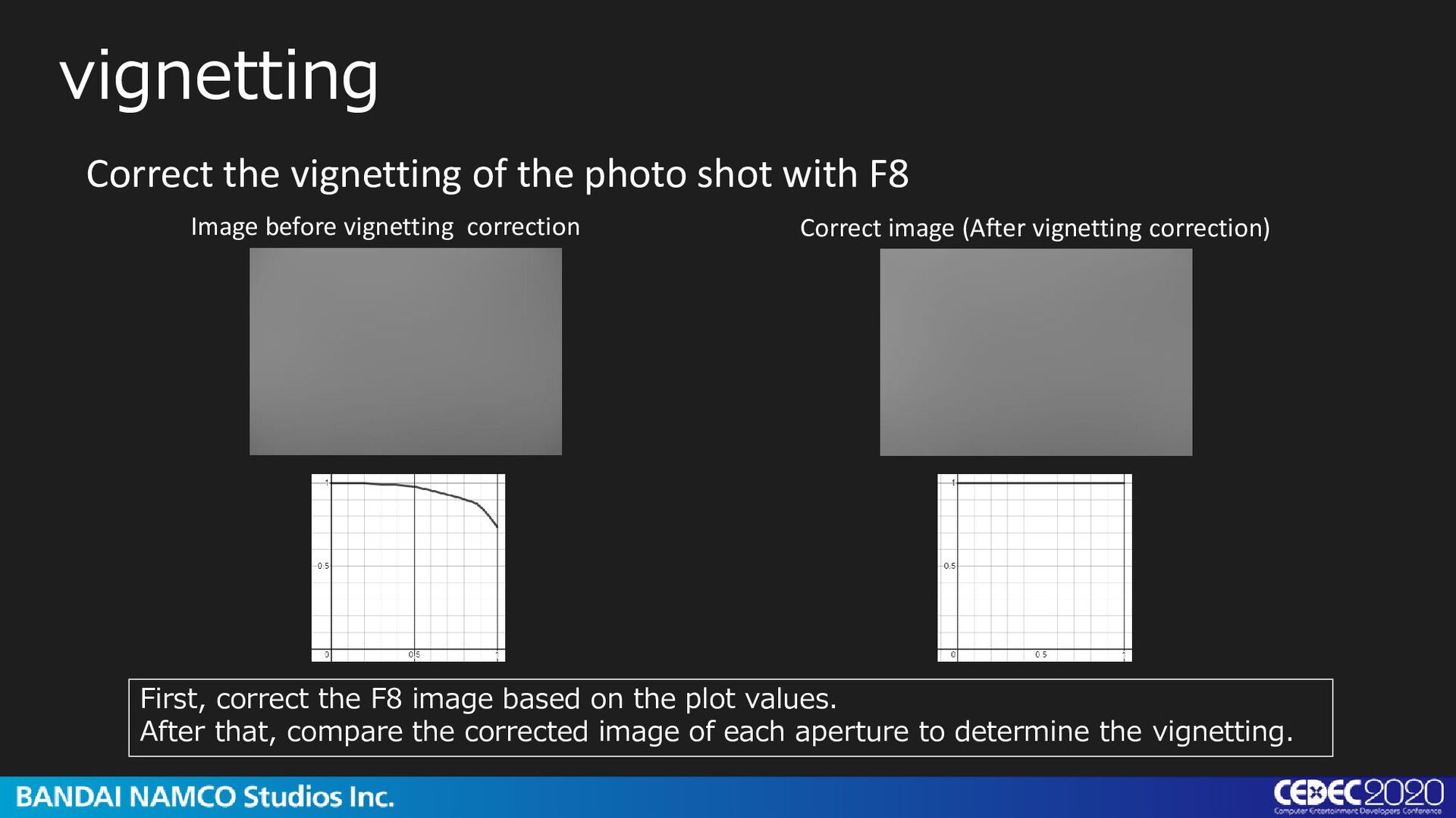
Correct the vignetting of the photo shot with F8 First, correct the F8 image based on the plot values. After that, compare the corrected image of each aperture to determine the vignetting.
vignetting. Posterization shows that vignetting is almost concentric circle. vignetting Correct image (After vignetting correction) ÷ F4 image vignetting at F4. = Here's an example: F4. F4 produces this kind of vignetting. And if you look at the posterization, you can see that the vignetting is almost concentric circle.
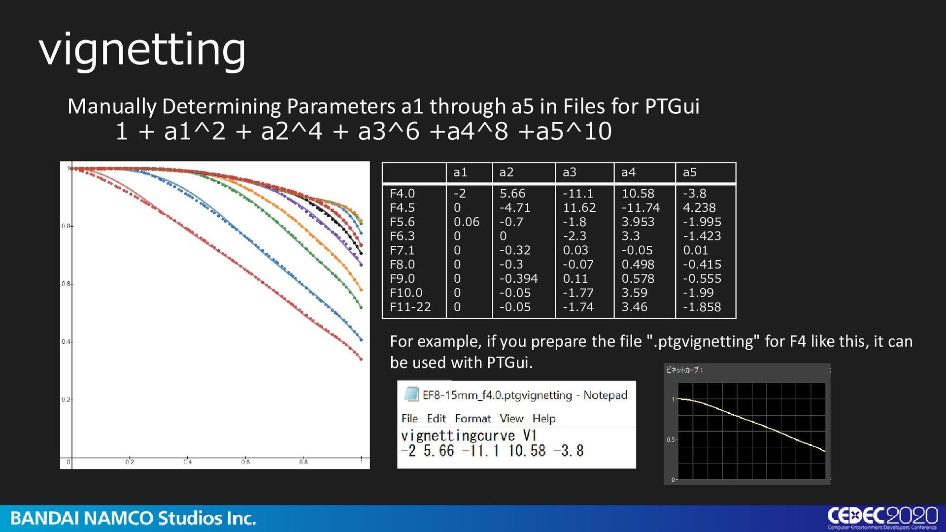
by PTGui. This is the expression, the curve described with 5 parameters. This was done manually using Desmos. The image on the bottom right shows the parameters of F4 loaded into PTGui. PTGui's automatic correction is estimated from the image, so it is less reliable than the measurement. Supplement I actually did this by copying and pasting result values in Desmos I moved the coefficient of the expression from a1 as a parameter to get a closer shape.
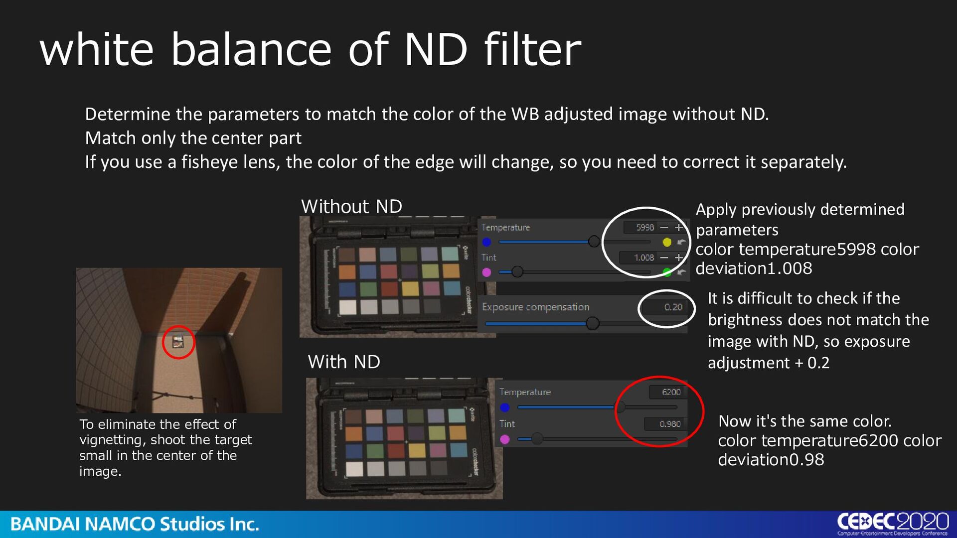
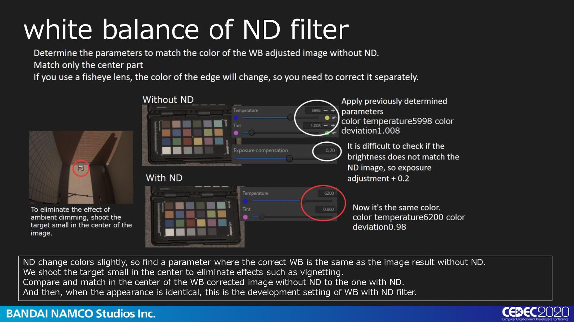
adjusted image without ND. Match only the center part If you use a fisheye lens, the color of the edge will change, so you need to correct it separately. white balance of ND filter Without ND It is difficult to check if the brightness does not match the image with ND, so exposure adjustment + 0.2 With ND Now it's the same color. color temperature6200 color deviation0.98 Apply previously determined parameters color temperature5998 color deviation1.008 To eliminate the effect of vignetting, shoot the target small in the center of the image.
find a parameter where the correct WB is the same as the image result without ND. We shoot the target small in the center to eliminate effects such as vignetting. Compare and match in the center of the WB corrected image without ND to the one with ND. And then, when the appearance is identical, this is the development setting of WB with ND filter.
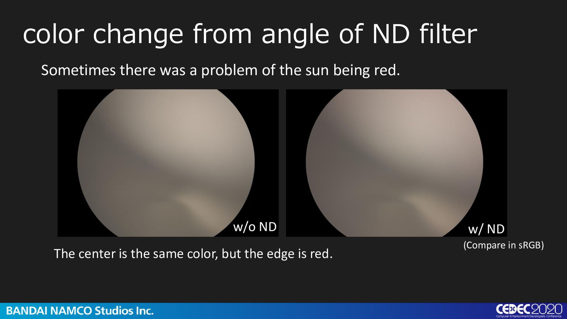
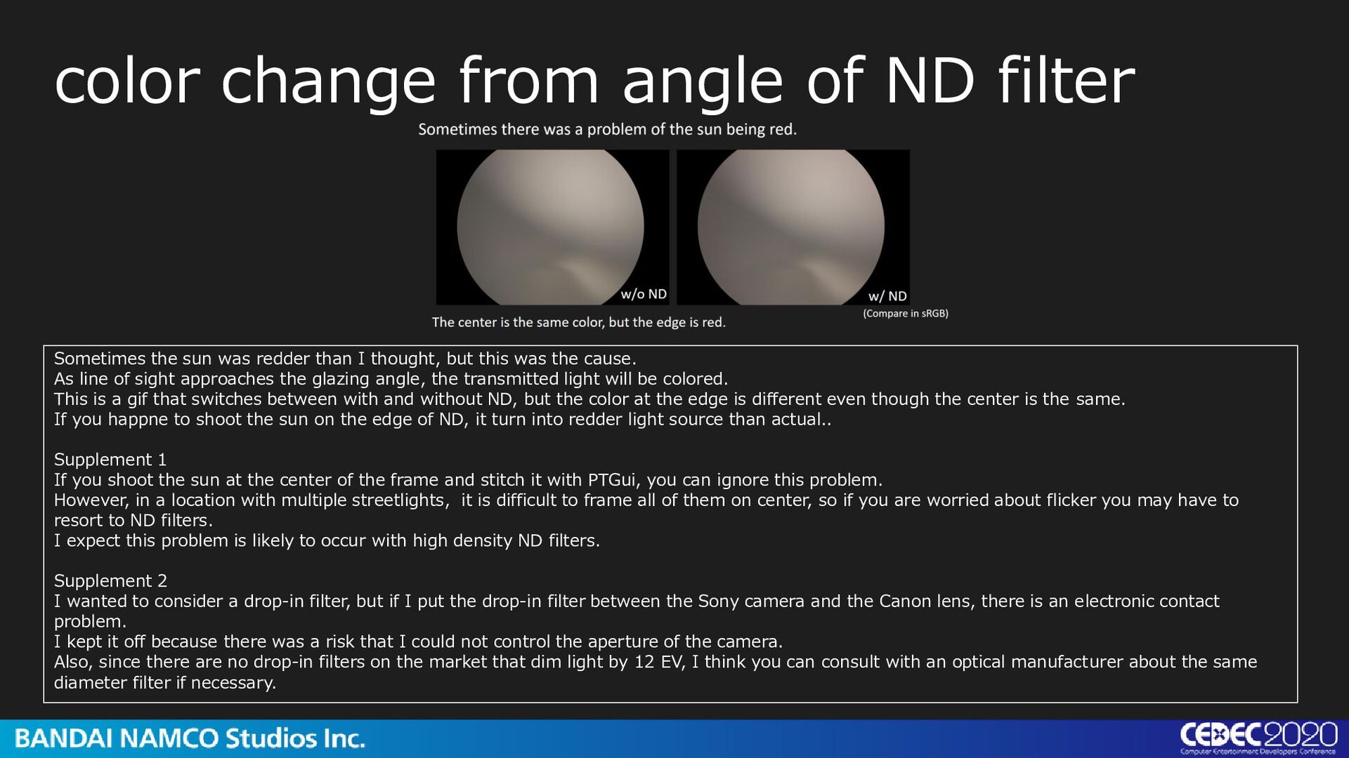
was redder than I thought, but this was the cause. As line of sight approaches the glazing angle, the transmitted light will be colored. This is a gif that switches between with and without ND, but the color at the edge is different even though the center is the same. If you happne to shoot the sun on the edge of ND, it turn into redder light source than actual.. Supplement 1 If you shoot the sun at the center of the frame and stitch it with PTGui, you can ignore this problem. However, in a location with multiple streetlights, it is difficult to frame all of them on center, so if you are worried about flicker you may have to resort to ND filters. I expect this problem is likely to occur with high density ND filters. Supplement 2 I wanted to consider a drop-in filter, but if I put the drop-in filter between the Sony camera and the Canon lens, there is an electronic contact problem. I kept it off because there was a risk that I could not control the aperture of the camera. Also, since there are no drop-in filters on the market that dim light by 12 EV, I think you can consult with an optical manufacturer about the same diameter filter if necessary.
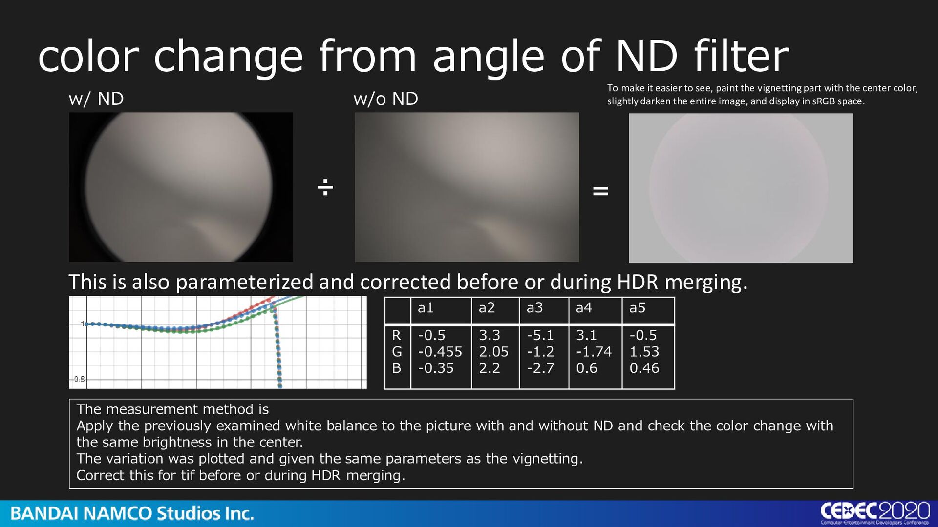
merging. color change from angle of ND filter w/ ND w/o ND ÷ = To make it easier to see, paint the vignetting part with the center color, slightly darken the entire image, and display in sRGB space. a1 a2 a3 a4 a5 R G B -0.5 -0.455 -0.35 3.3 2.05 2.2 -5.1 -1.2 -2.7 3.1 -1.74 0.6 -0.5 1.53 0.46 The measurement method is Apply the previously examined white balance to the picture with and without ND and check the color change with the same brightness in the center. The variation was plotted and given the same parameters as the vignetting. Correct this for tif before or during HDR merging.
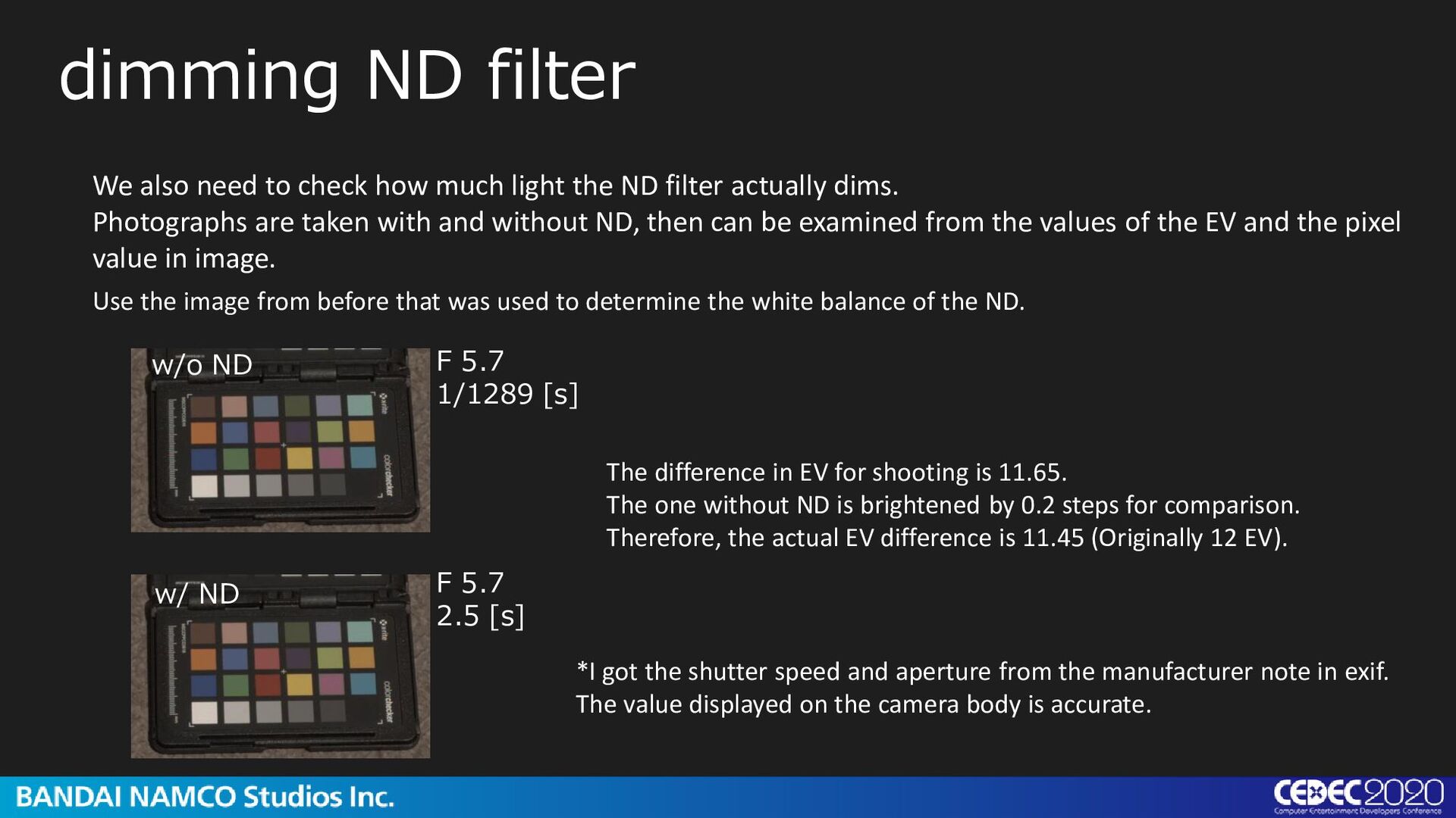
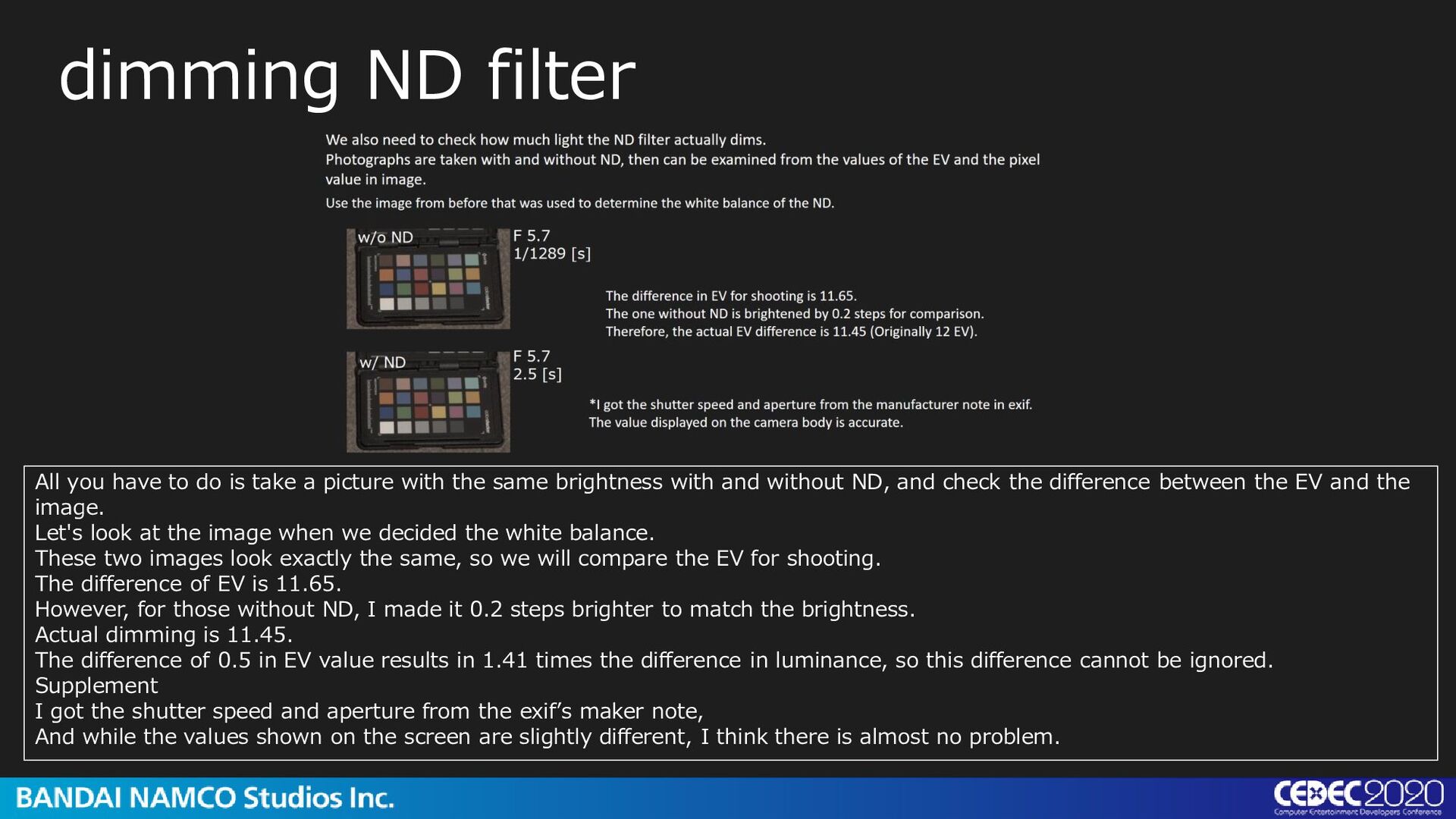
filter actually dims. Photographs are taken with and without ND, then can be examined from the values of the EV and the pixel value in image. dimming ND filter w/o ND w/ ND Use the image from before that was used to determine the white balance of the ND. F 5.7 1/1289 [s] F 5.7 2.5 [s] The difference in EV for shooting is 11.65. The one without ND is brightened by 0.2 steps for comparison. Therefore, the actual EV difference is 11.45 (Originally 12 EV). *I got the shutter speed and aperture from the manufacturer note in exif. The value displayed on the camera body is accurate.
a picture with the same brightness with and without ND, and check the difference between the EV and the image. Let's look at the image when we decided the white balance. These two images look exactly the same, so we will compare the EV for shooting. The difference of EV is 11.65. However, for those without ND, I made it 0.2 steps brighter to match the brightness. Actual dimming is 11.45. The difference of 0.5 in EV value results in 1.41 times the difference in luminance, so this difference cannot be ignored. Supplement I got the shutter speed and aperture from the exif’s maker note, And while the values shown on the screen are slightly different, I think there is almost no problem.
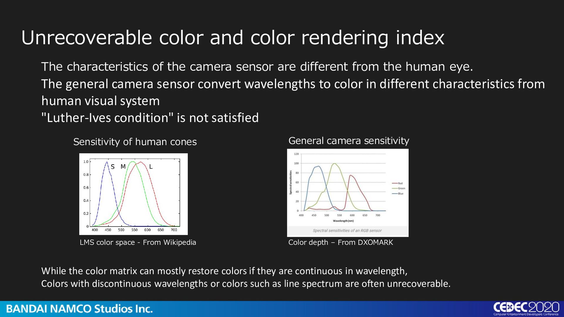
human eye. The general camera sensor convert wavelengths to color in different characteristics from human visual system "Luther-Ives condition" is not satisfied Unrecoverable color and color rendering index Sensitivity of human cones General camera sensitivity While the color matrix can mostly restore colors if they are continuous in wavelength, Colors with discontinuous wavelengths or colors such as line spectrum are often unrecoverable. LMS color space - From Wikipedia Color depth – From DXOMARK
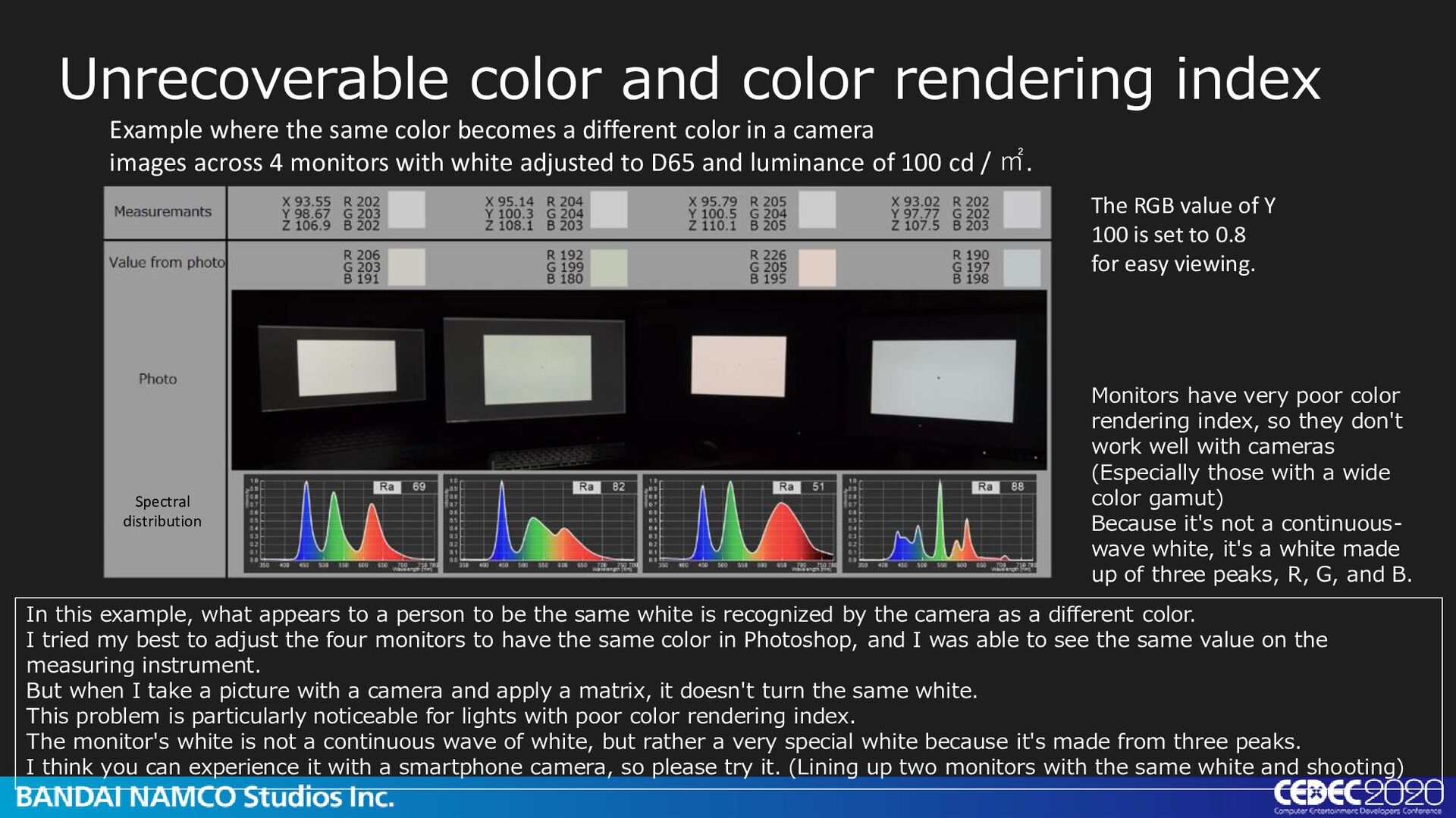
appears to a person to be the same white is recognized by the camera as a different color. I tried my best to adjust the four monitors to have the same color in Photoshop, and I was able to see the same value on the measuring instrument. But when I take a picture with a camera and apply a matrix, it doesn't turn the same white. This problem is particularly noticeable for lights with poor color rendering index. The monitor's white is not a continuous wave of white, but rather a very special white because it's made from three peaks. I think you can experience it with a smartphone camera, so please try it. (Lining up two monitors with the same white and shooting) Example where the same color becomes a different color in a camera images across 4 monitors with white adjusted to D65 and luminance of 100 cd / ㎡. The RGB value of Y 100 is set to 0.8 for easy viewing. Monitors have very poor color rendering index, so they don't work well with cameras (Especially those with a wide color gamut) Because it's not a continuous- wave white, it's a white made up of three peaks, R, G, and B. Spectral distribution
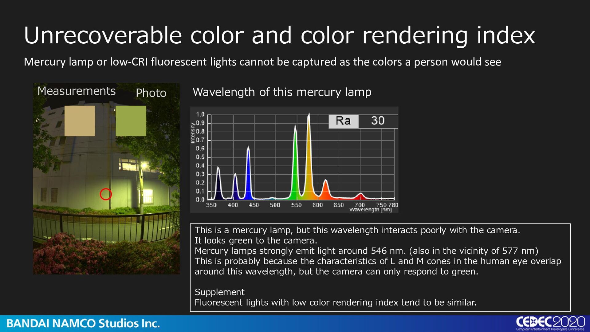
the colors a person would see Wavelength of this mercury lamp Unrecoverable color and color rendering index Measurements Photo This is a mercury lamp, but this wavelength interacts poorly with the camera. It looks green to the camera. Mercury lamps strongly emit light around 546 nm. (also in the vicinity of 577 nm) This is probably because the characteristics of L and M cones in the human eye overlap around this wavelength, but the camera can only respond to green. Supplement Fluorescent lights with low color rendering index tend to be similar.
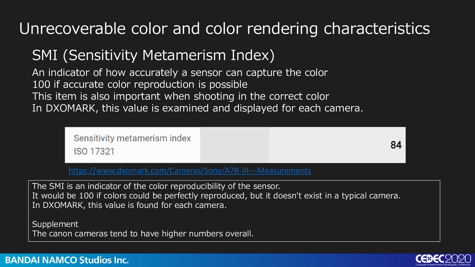
An indicator of how accurately a sensor can capture the color 100 if accurate color reproduction is possible This item is also important when shooting in the correct color In DXOMARK, this value is examined and displayed for each camera. https://www.dxomark.com/Cameras/Sony/A7R-III---Measurements The SMI is an indicator of the color reproducibility of the sensor. It would be 100 if colors could be perfectly reproduced, but it doesn't exist in a typical camera. In DXOMARK, this value is found for each camera. Supplement The canon cameras tend to have higher numbers overall.
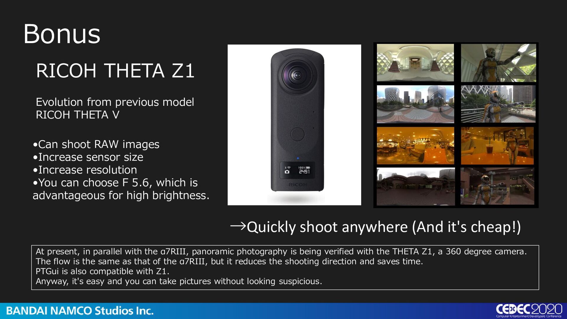
images •Increase sensor size •Increase resolution •You can choose F 5.6, which is advantageous for high brightness. RICOH THETA Z1 Evolution from previous model RICOH THETA V At present, in parallel with the α7RIII, panoramic photography is being verified with the THETA Z1, a 360 degree camera. The flow is the same as that of the α7RIII, but it reduces the shooting direction and saves time. PTGui is also compatible with Z1. Anyway, it's easy and you can take pictures without looking suspicious.
ND to capture the brightness of the sun. To convert the sun to directional light, we need to mesurement separately or shooting only the sun. white balance (RawTherapee Parameter) color temperature=5921 color deviation=0.934 luminance restoration factor 1.07 color matrix Matrix 0.6092 0.2548 0.0846 0.1714 1.0547 -0.2138 0.0436 -0.4651 1.5097 ICC profile primary R G B 0.5954 0.1664 0.0396 0.3578 1.0430 -0.3465 -0.0054 -0.2197 1.1124 vignetting F2.1 F3.5 F5.6 -0.15 0.07 -2.1 13.7 -21.5 0 -0.6 -0.43 8.7 -15.3 -0.02 -0.3 1.2 -1.7 -2 Supplement 1: The luminance recovery factor will vary slightly depending on the light source used. Supplement 2: The vignetting of THETA Z1 was not as dimmed as I expected. It's just a quick measurement, so it may not be that accurate.
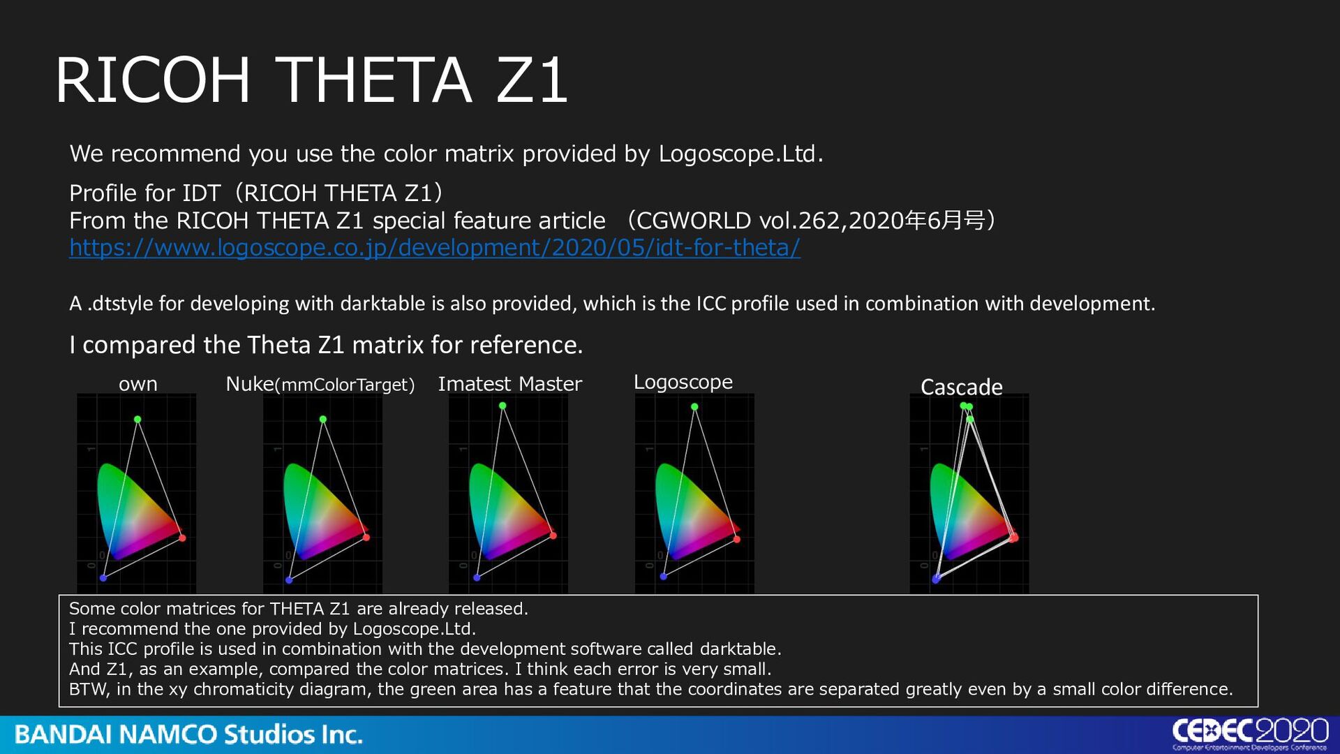
RICOH THETA Z1 I compared the Theta Z1 matrix for reference. own Profile for IDT(RICOH THETA Z1) From the RICOH THETA Z1 special feature article (CGWORLD vol.262,2020年6月号) https://www.logoscope.co.jp/development/2020/05/idt-for-theta/ A .dtstyle for developing with darktable is also provided, which is the ICC profile used in combination with development. Nuke(mmColorTarget) Imatest Master Logoscope Cascade Some color matrices for THETA Z1 are already released. I recommend the one provided by Logoscope.Ltd. This ICC profile is used in combination with the development software called darktable. And Z1, as an example, compared the color matrices. I think each error is very small. BTW, in the xy chromaticity diagram, the green area has a feature that the coordinates are separated greatly even by a small color difference.
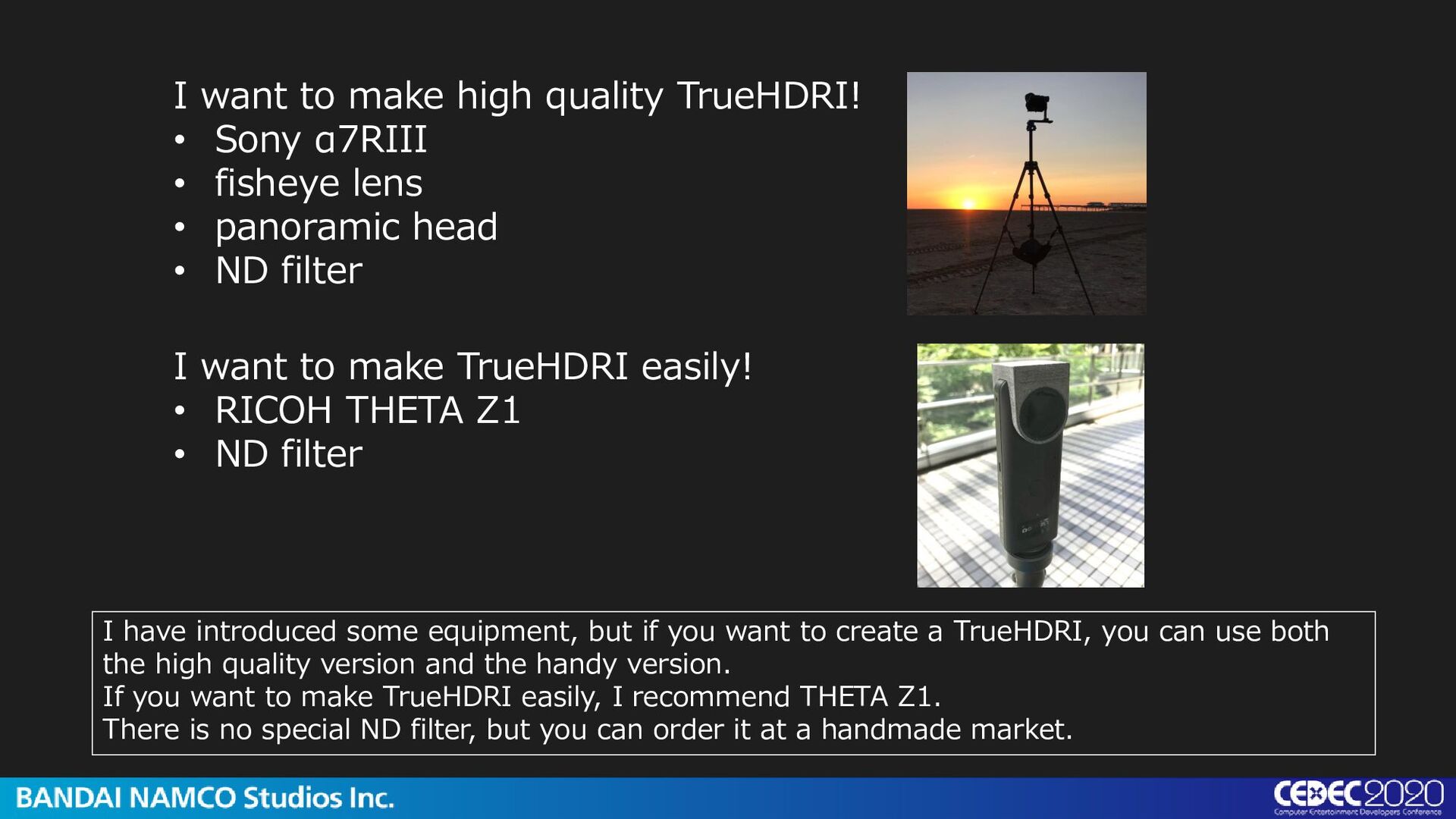
• fisheye lens • panoramic head • ND filter I want to make TrueHDRI easily! • RICOH THETA Z1 • ND filter I have introduced some equipment, but if you want to create a TrueHDRI, you can use both the high quality version and the handy version. If you want to make TrueHDRI easily, I recommend THETA Z1. There is no special ND filter, but you can order it at a handmade market.
important to make accurate measurements first. It seems difficult to measure, but once the equipment is decided, it is measured only once. After that, as long as you take pictures with the same camera, you don’t have to repeat measurements. Supplement Actually, I feel that ND may deteriorate over time.
can be done based on correct lighting • Specifications that accurately recreate color, brightness, including even light • Along with accuracy, “Convenient workflow” is also important →TrueHDRI has both these qualities.
production Therefore, we will disclose this technology’s specifications and data →Currently available on CEDiL. Download here. https://cedil.cesa.or.jp/cedil_sessions/view/2329 We hope that you will take this opportunity to shoot pictures of various locations and enjoy the creation of HDRI.
![Color grading 1/125[s] 1/250[s] 1/1000[s] 1/2000[s] Also, because reference brightness](https://files.speakerdeck.com/presentations/98567313c1cc4ebcbe09eeaa56014bab/slide_28.jpg)
![Maya[Arnold] with TrueHDRI Correct colors and brightness This is a](https://files.speakerdeck.com/presentations/98567313c1cc4ebcbe09eeaa56014bab/slide_55.jpg)
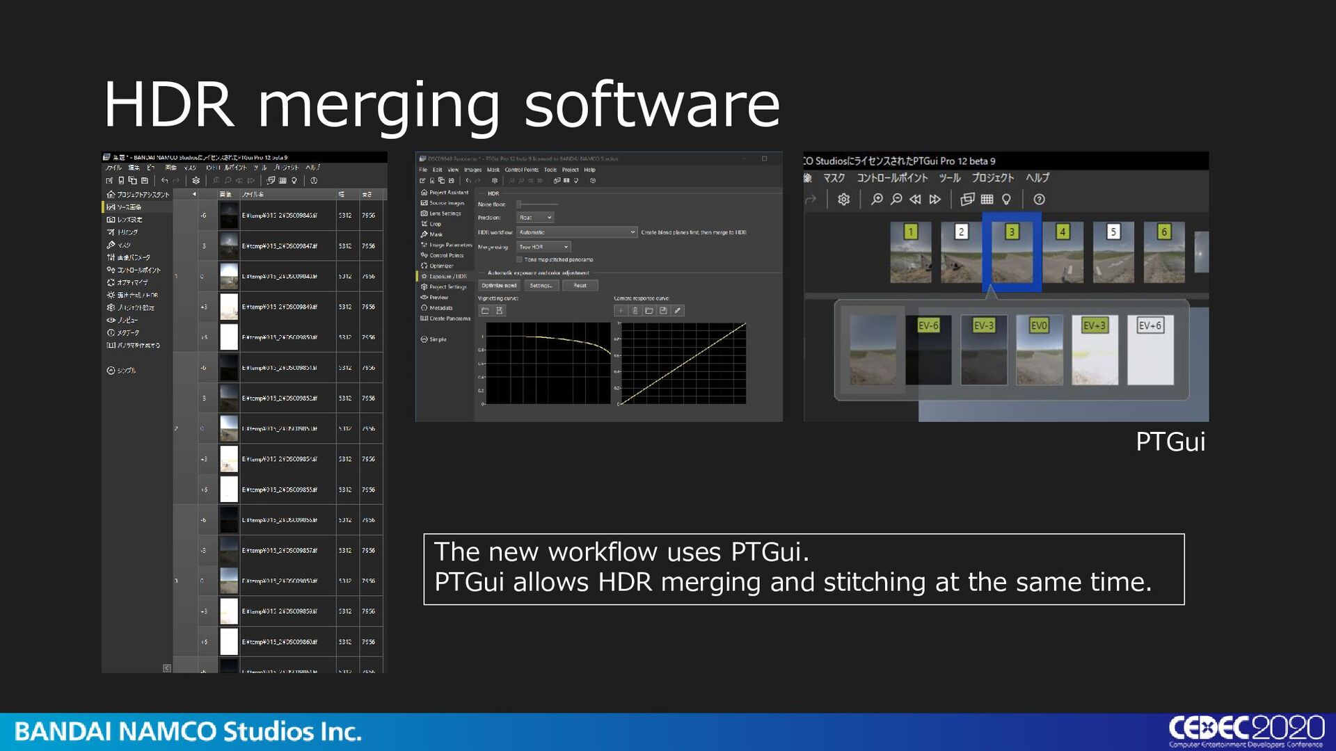
![HDR merging software inhouse tools [RAW to HDR] I used](https://files.speakerdeck.com/presentations/98567313c1cc4ebcbe09eeaa56014bab/slide_121.jpg)